
Casing for electronic device and projector having this casing for electronic device

A technology of electronic equipment and projectors, which is applied in the field of projectors, can solve problems such as time-consuming, complicated frame molding process, and inconvenient use of projectors, and achieve the effect of simplifying the molding process and manufacturing process and reducing the number of parts

Inactive Publication Date: 2005-08-24
SEIKO EPSON CORP
View PDF1 Cites 18 Cited by
  • Summary
  • Abstract
  • Description
  • Claims
  • Application Information

AI Technical Summary

Problems solved by technology

[0005] However, in the leg portion structure described in the above-mentioned Patent Document 1, when molding the frame body by injection molding or the like, the nut must be insert-molded, which may complicate the frame body molding process.
[0006] In addition, due to the simple threaded connection of bolts and nuts, it is possible for the user to store the projector with the inclination adjustment legs screwed into the innermost state.
Therefore, when using it next time, it is necessary to adjust the amount of protrusion again due to the relationship with the fixed leg portion, and there is inconvenience in the use of the projector.
[0007] Furthermore, after the projector is manufactured, when it is packaged and shipped, it is necessary to match the pads and the like to the legs for tilt adjustment, and to match the protrusion of the fixed legs so that the inside does not shake and become unstable. , so there is a problem of time-consuming packaging operations

Method used


Image

  • Casing for electronic device and projector having this casing for electronic device
  • Casing for electronic device and projector having this casing for electronic device
  • Casing for electronic device and projector having this casing for electronic device

Examples


Embodiment Construction

[0050] Hereinafter, an embodiment of the present invention will be described with reference to the drawings.

[0051] 1. The main components of the projector

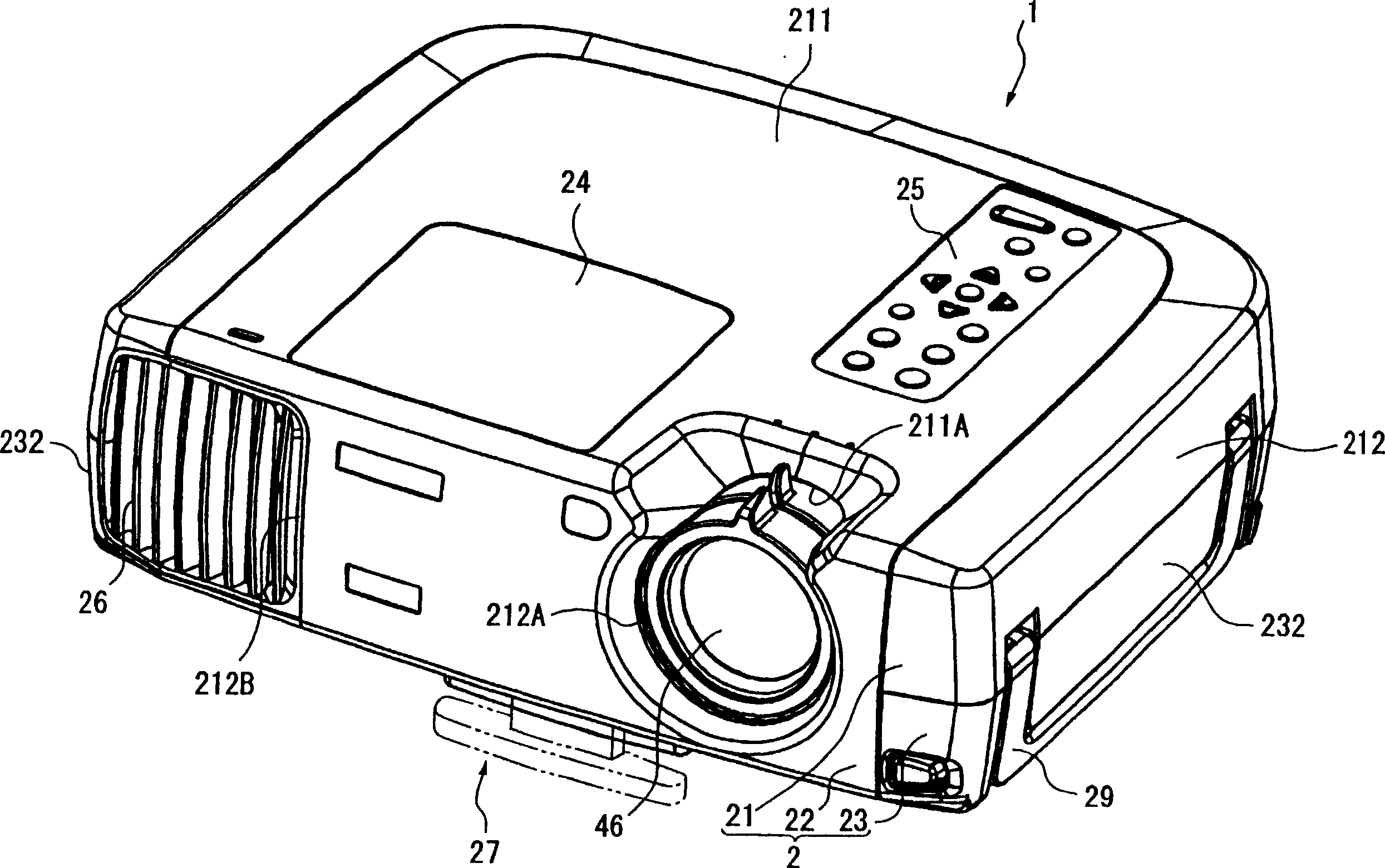
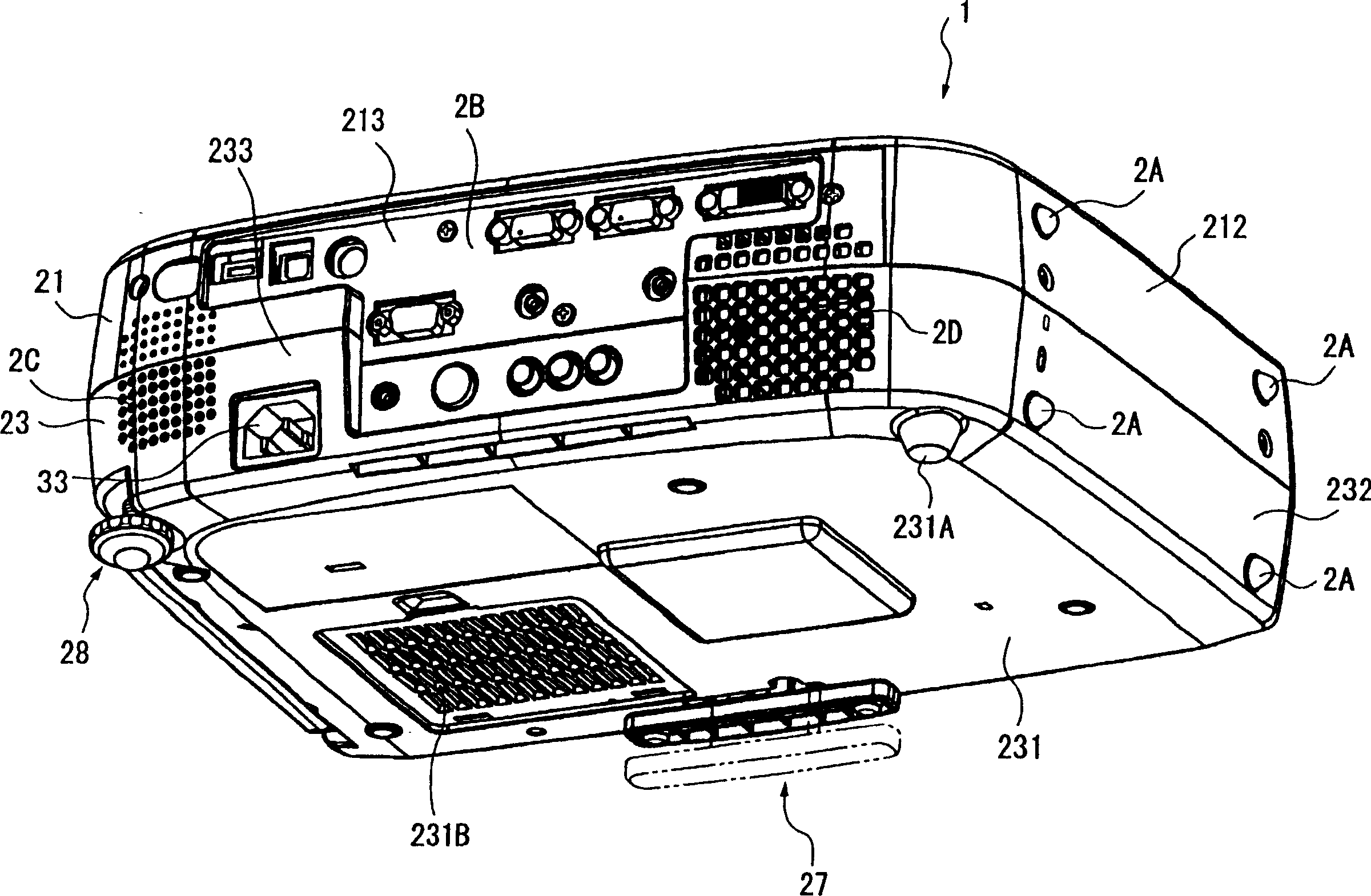
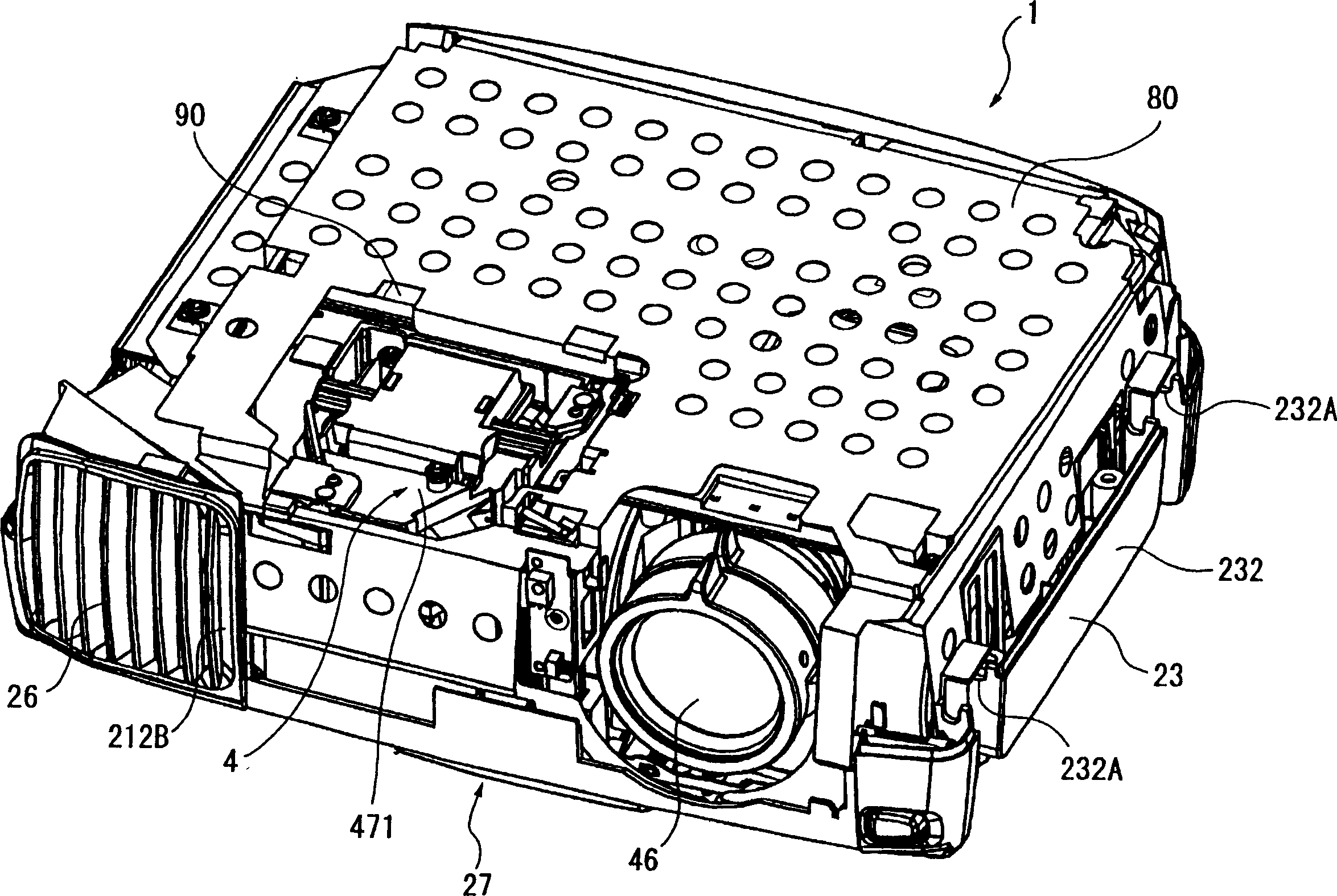
[0052] figure 1 It is an overall perspective view of the projector 1 according to the present embodiment viewed from above, figure 2 is an overall perspective view of the projector 1 viewed from below, Figure 3 ~ Figure 5 It is a perspective view showing the inside of the projector 1 . in particular, image 3 From figure 1 In the state in which the upper casing 21 of the projector 1 is removed, Figure 4 From image 3 In the state, the shield plate 80 and the drive plate 90 are removed and viewed from the rear side, Figure 5 From Figure 4 Figure 4 is removed from the state.

[0053] like Figure 1 ~ Figure 3 As shown, the projector 1 as an electronic device includes: an outer frame 2, which is a frame for electronic equipment; a power supply part 3, which is accommodated in the outer frame 2; an optical pa...


PUM


Abstract

Provided are a casing for electronic device and a projector. The casing for electronic device having a casing body for housing an electronic device and a foot part provided to be movable forward to and backward from a surface of the casing body and adapted to adjust inclination of the electronic device, the casing body has a boss that is formed to protrude on the inner surface of the casing body and in which a hole connecting the inside and outside of the casing body is formed, and the foot part has a grounding part exposed from the casing for an electronic device and abutted against an installation target surface and a shaft part housed within the boss and having a screw groove formed on its outer circumferential surface. A recess part is formed at a part of the screw groove of the shaft part, and on the inner surface of the boss, a screw thread that engages with the screw groove of the shaft part, has its part cut out in the circumferential direction and is formed within a range of not overlapping on the circumference of the hole as viewed from the direction of moving forward and backward of the foot part, and a protrusion that fits in the recess part when the shaft part turns by a predetermined quantity in relation to the inner surface of the boss, are formed.

Description

technical field [0001] The present invention relates to a housing for electronic equipment provided with a housing main body for accommodating electronic equipment and a leg portion configured to be capable of The inclination of the above-mentioned electronic equipment is adjusted when it enters and exits from the main body surface of the housing and is installed on the installation surface. Background technique [0002] Conventionally, projectors have been used for demonstration occasions such as conferences, societies, and exhibitions, and for viewing movies at home. This type of projector forms an optical image by modulating a light beam emitted from a light source provided in an outer casing according to image information, and enlarges and projects the optical image. [0003] Such a projector is known as a projector provided with a leg portion for adjusting the inclination in order to properly project an optical image on a screen or the like (for example, refer to Paten...

Claims


Application Information

Patent Timeline
IPC IPC(8): G03B21/00G03B21/14H05K5/00H05K5/02
CPCH05K5/0234
Inventor 大越正行百濑明
Owner SEIKO EPSON CORP
Learn More