
Hollow waveguide sector antenna

A waveguide antenna, hollow technology, applied in the direction of leaky waveguide antenna, antenna, antenna array, etc., can solve the problem that the fan-shaped characteristic cannot be realized by the antenna, and achieve the effect of large bandwidth

Inactive Publication Date: 2005-08-17
TELEFON AB LM ERICSSON (PUBL)
View PDF1 Cites 3 Cited by
  • Summary
  • Abstract
  • Description
  • Claims
  • Application Information

AI Technical Summary

Problems solved by technology

The sectoring characteristic cannot be achieved by this prior art antenna

Method used


Image

  • Hollow waveguide sector antenna
  • Hollow waveguide sector antenna
  • Hollow waveguide sector antenna

Examples


Embodiment Construction

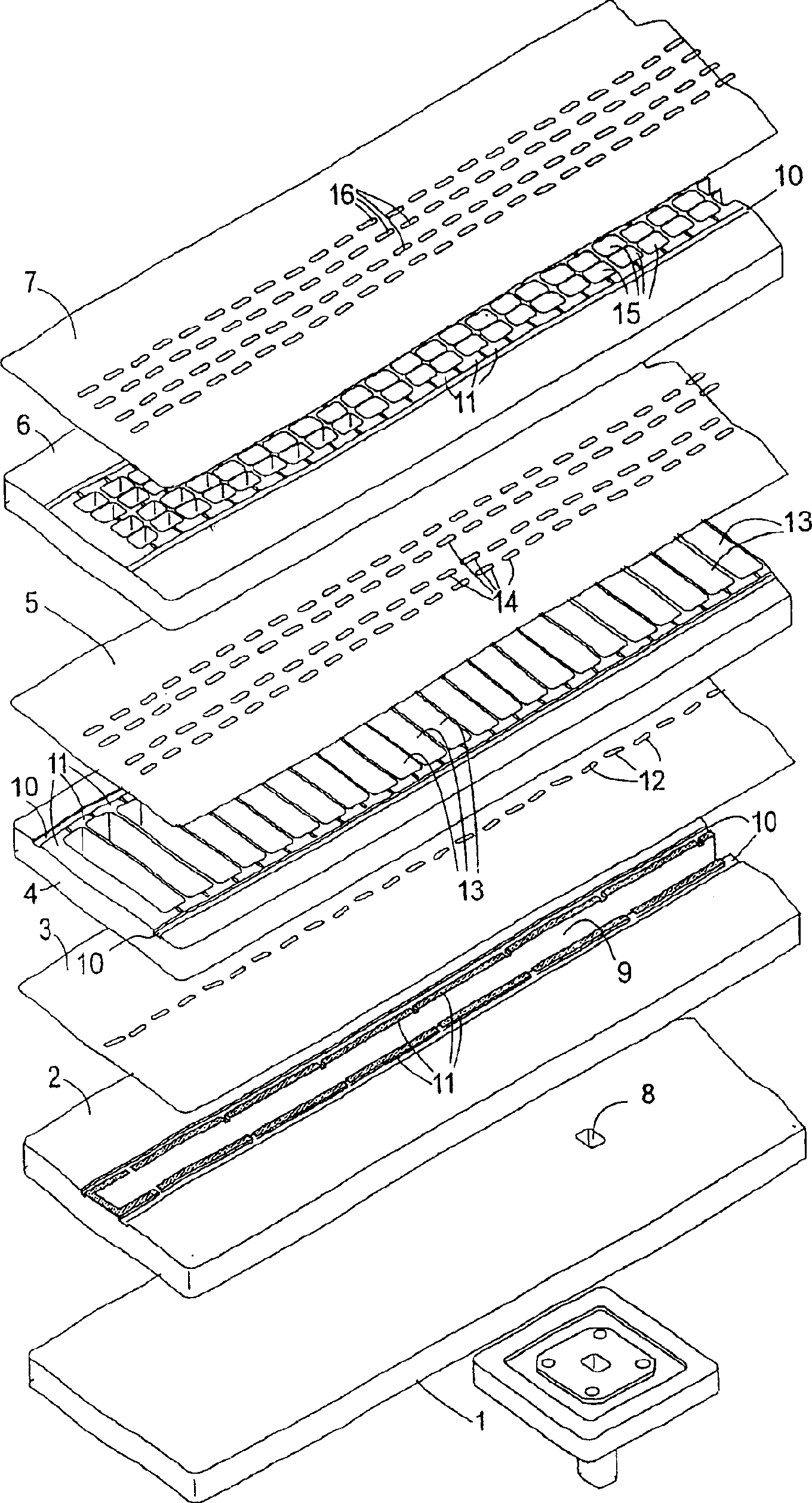
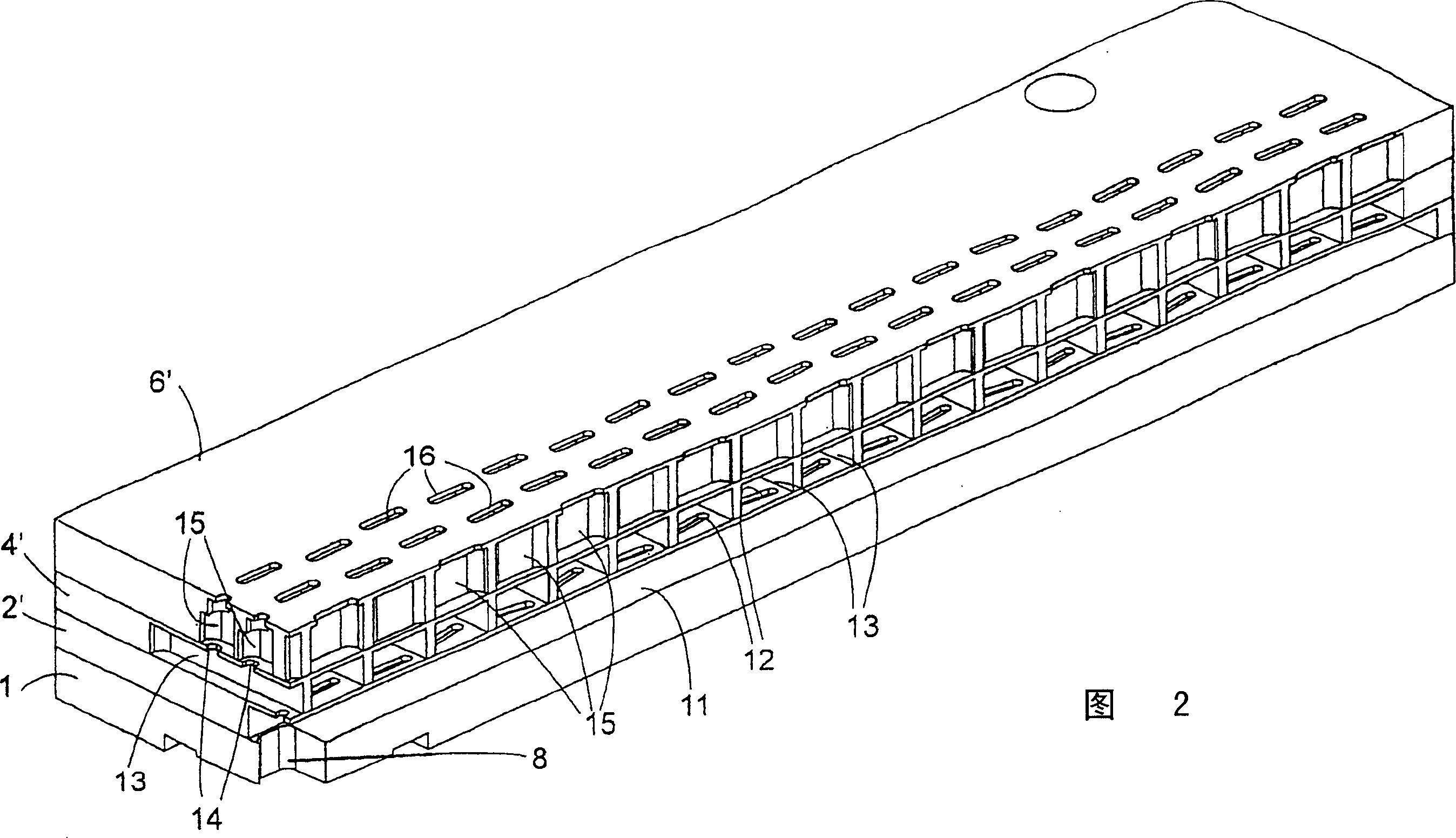
[0043] refer to figure 1 A first embodiment of the sector antenna of the present invention will be described. The figure shows a plurality of metal plates 1-7, whereby the antenna forms a stacked structure. The board 1 indicated at the bottom position in the figure has a hole 8 and is arranged as a connection flange for connecting a tubular hollow waveguide so that an RF signal transmitted through an antenna is fed or an RF signal received by it is extracted to the bottom side of the board 1 at the hole 8 . In the description, only the aspect of transmission using the antenna of the present invention is considered, but it will be understood that the antenna can be used without adjustment for receiving RF signals.

[0044] In the board 2 arranged on the board 1, a first hollow waveguide referred to as a longitudinal hollow waveguide extends in the longitudinal direction. Via the opening 8 the first hollow waveguide is fed with an RF signal which propagates in the first longi...


PUM


Abstract

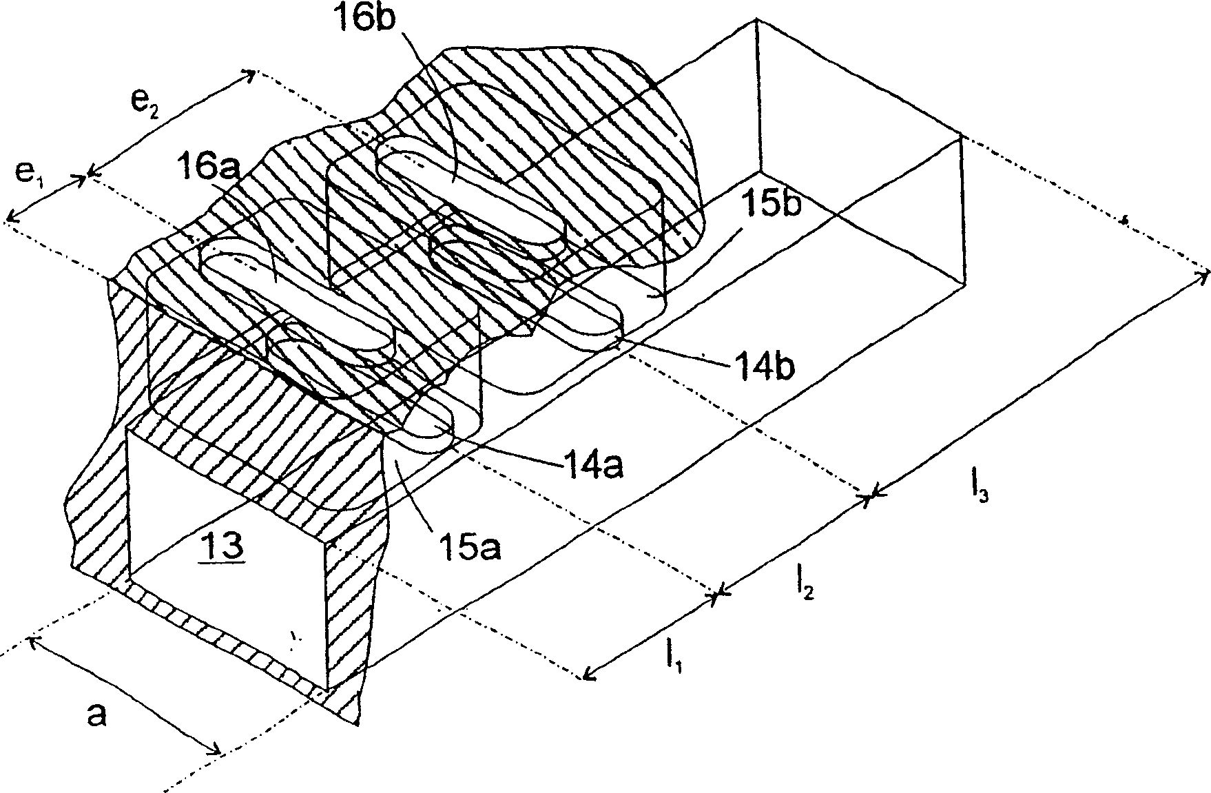
A hollow waveguide group antenna comprises a hollow waveguide extending in a direction in space and a plurality of chambers, each of which has a sending / receiving slit and is coupled to the hollow waveguide by a coupling slit. The sending / receiving slits are distributed at a fixed distance from each other, and the distribution of the coupling slits in the direction in space at the transversal hollow waveguide is selected differently from the distribution of the sending / receiving slits such that a wave propagating at the working frequency excites the sending / receiving slits with amplitudes and phases suitable for realizing a sector direction characteristic. The fixed distance is approximately 0.5lambda0 for 90° sector direction characteristic and approximately 0.64 lambda0 for a 45° sector direction characteristic.

Description

technical field [0001] The invention relates to a sector antenna. Background technique [0002] The performance required for a sector antenna for wireless transmission is very high. They uniformly cover a certain range such as a 90° sector, with reduced sidelobe intensity in the horizontal plane, and strong directivity without zero-point characteristics in the vertical plane. From H.Ansorgen, M.Guttenberger, K-H.Mierzwjak, U.Oehler, H.Tell, "Antenna solutions for point to multi-point radio systems" ECCR, Bologna 1996 and M.Guttenberger, H.Tell, U.Oehler, " Microstrip-Gruppenantennen mit shcarf sektorisierenden Eigen-schaftenals Zentralstationsantennen Fur Punket zu MultipunktSysteme", ITG Fachtagung Antennen Munchen 1998, it is known to realize such sectoral antennas in strip technology. [0003] A common problem with such traditional sectored antennas is that cross-polarization is not adequately suppressed. [0004] In order to achieve the desired directional properties ...

Claims


Application Information

Patent Timeline
Patent Type & Authority Applications(China)
IPC IPC(8): H01Q21/00
CPCH01Q21/06H01Q21/28H01Q21/064H01Q13/0233H01Q13/22H01Q21/005
Inventor M·蒙克
Owner TELEFON AB LM ERICSSON (PUBL)
Learn More