
Eather net networking matrix switching system

A matrix switching, Ethernet technology, applied in CCTV systems, network interconnection, data exchange through path configuration, etc., can solve problems such as low data transmission rate, monitoring system can not meet customer needs, expansion difficulties, etc. Achieving the effect of high data transmission rate

Inactive Publication Date: 2005-08-03
SHENZHEN INFINOVA
View PDF0 Cites 1 Cited by
  • Summary
  • Abstract
  • Description
  • Claims
  • Application Information

AI Technical Summary

Problems solved by technology

[0002] Since black-and-white cameras and televisions were available, television monitoring systems have been developed. It is widely used in security, management and other occasions. After continuous development and improvement, it has developed from single-point and single-line models to multi-point monitoring systems. With the continuous development of the industry and the continuous expansion of the system scale, the monitoring system constructed by a single matrix switching system is increasingly unable to meet the needs of customers
This results in a matrix switching system networked by RS232 and RS422 / RS485, but the limitations of this type of network are low data transmission rate, limited transmission distance, and the need to use external equipment, and the connection is complicated and difficult to expand. It is used in large-scale system fields, and each manufacturer uses its own unique protocol, which cannot guarantee universality

Method used

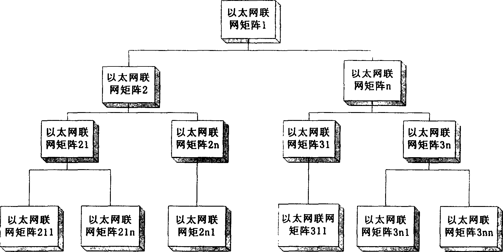

Image

  • Eather net networking matrix switching system
  • Eather net networking matrix switching system
  • Eather net networking matrix switching system

Examples


Embodiment 1

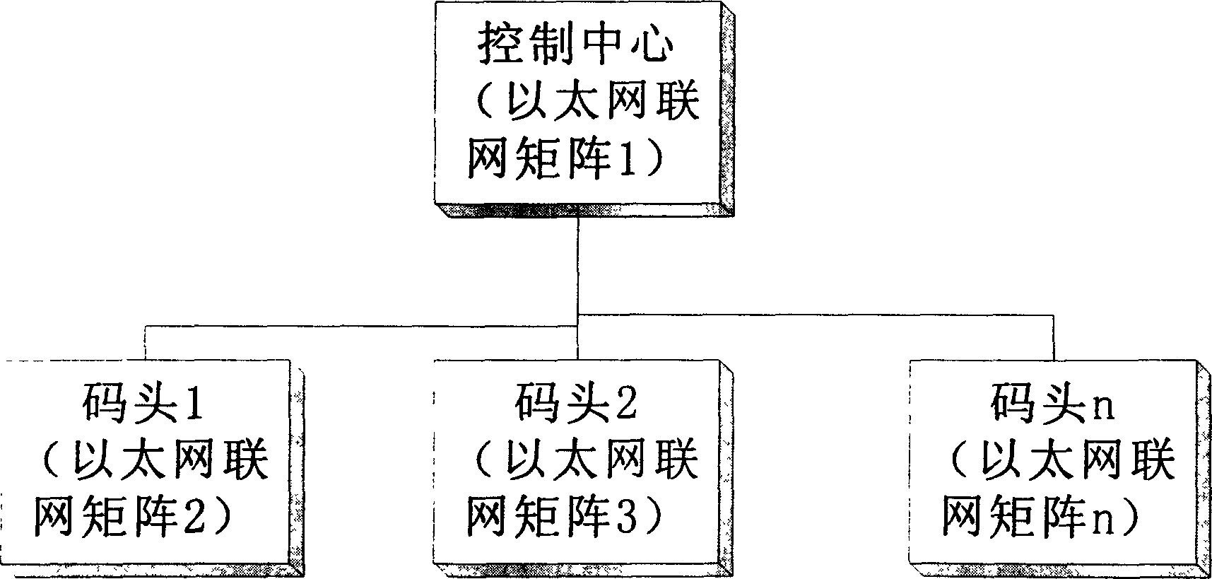
[0028] This example is to apply the Ethernet networking matrix switching system of the present invention in a port (see figure 2 ). This is a secondary networking system. In this system, an Ethernet networking matrix switching system (matrix 1) is arranged in the control center as the central matrix, and an Ethernet networking matrix switching system (matrix 2 to matrix n) is arranged at each terminal. The matrix of each terminal is An independent and complete system, they have their own alarm equipment, camera, pan / tilt, auxiliary equipment, video recorder, monitor, etc., and can work normally without a central control matrix. The central control matrix is ​​also an independent and complete system, but it can view the images of all cameras in each dock through network calls, and can control the actions of these cameras, such as turning, calling / setting preset positions, and controlling auxiliary switches. The alarm signal of the terminal can be transmitted to the central m...

Embodiment 2

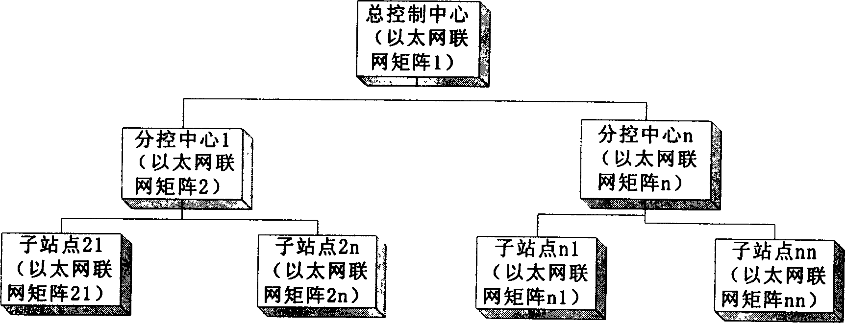
[0030] This example is a highway application Ethernet networking matrix switching system of the present invention (see image 3 ). This system is a three-level network. It has a general control center, several sub-control centers, and several sub-sites under each sub-control center. The customer requires that the general control center can view the images of all sub-control centers under the control and the images of each sub-site under the sub-control center, and the sub-control center can view and control the images of each sub-site under the control, and the alarms of all stations must be able to be transmitted to the superior control center. Therefore, an Ethernet networking matrix switching system (matrix 1) is arranged in the main control center for overall control and the safety protection of the main control center itself; each sub-control center also arranges an Ethernet networking matrix switching system (matrix 2 to matrix n), used to control the safety protectio...


PUM


Abstract

An Ethernet on-line matrix switching system includes: a computer network, Ethernet and on-line matrix switching system includes: an independent Ethernet on-line matrix switching systems by computer networks, carrying out data transmission by standard TCP / IP protocol, a video channel registering the detailed path passed by a remote video signal arriving at the local, said path includes IP address of Ethernet on-line matrix switching system and video input and output nodes numbers, a switching module forwarding with self-defined signals and a pyramid connection structure of the system.

Description

technical field [0001] The invention relates to a television monitoring matrix switching system, in particular to a networked television monitoring matrix switching system, specifically an Ethernet networking matrix switching system. Background technique [0002] Since black-and-white cameras and televisions were available, television monitoring systems have been developed. It is widely used in security, management and other occasions. After continuous development and improvement, it has developed from single-point and single-line models to multi-point monitoring systems. With the continuous development of the industry and the continuous expansion of the system scale, the monitoring system constructed by a single matrix switching system is increasingly unable to meet the needs of customers. This results in a matrix switching system networked by RS232 and RS422 / RS485, but the limitations of this type of network are low data transmission rate, limited transmission distance, an...

Claims


Application Information

Patent Timeline
Patent Type & Authority Applications(China)
IPC IPC(8): H04L12/46H04N7/18
Inventor 刘肇怀
Owner SHENZHEN INFINOVA
Learn More