
Observation device for soil characteristic and observation method for soil characteristicp

An observation device and detection device technology, which is applied in botany equipment and methods, soil preparation methods, soil material testing, etc., can solve errors, detection components and samples are easily affected by the outside world, and data accuracy and reproducibility are poor And other issues

Inactive Publication Date: 2005-07-27
NOKODAI TLO KK
View PDF1 Cites 4 Cited by
  • Summary
  • Abstract
  • Description
  • Claims
  • Application Information

AI Technical Summary

Problems solved by technology

[0009] However, when sensors with different detection principles are used to detect multiple parameters in real time, due to the limitation of the installation position, various characteristics related to the soil are detected at positions where the sensors are separated from each other.
In this way, it cannot be guaranteed that the various characteristics detected are the characteristics of the same sample.
[0010] In addition, including the device described in the above publication, when grasping the distribution of soil properties in the farm, in the case of using a device that directly measures (detects) parameters reflecting soil properties on the spot, the detection element and the sample ( The relationship between soil) is susceptible to errors caused by external influences
For example, when detection is performed with the detection element in contact with the soil, it is easy to produce a change in the contact pressure between the detection element and the soil. On the other hand, when the detection element is separated from the soil for detection, it is easy to The distance between the detection element and the soil changes, so the accuracy and reproducibility of the data obtained under the influence of external factors are very poor

Method used


Image

  • Observation device for soil characteristic and observation method for soil characteristicp
  • Observation device for soil characteristic and observation method for soil characteristicp
  • Observation device for soil characteristic and observation method for soil characteristicp

Examples


no. 1 example

[0074] Next, a first embodiment of the soil characteristic observation device of the present invention will be described with reference to the drawings.

[0075] (Outline of detection system)

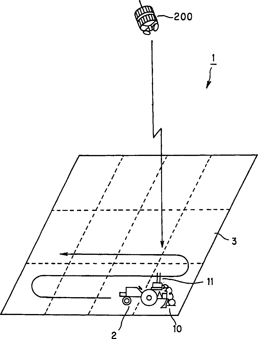
[0076] figure 1 In , the observation system of this embodiment is schematically shown.

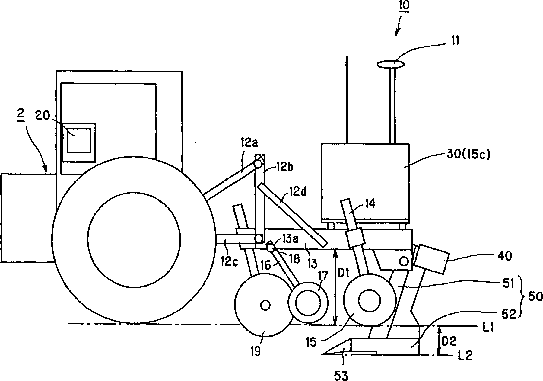
[0077] Such as figure 1As shown, the detection system 1 is drawn by a vehicle 2 such as a tractor, and it is composed of a soil characteristic observation device 10 that moves in a farm 3 to be cultivated for crop production, and a GPS (Global Positioning System) for grasping the correct position of the soil characteristic observation device 10. system) satellites. The soil property observation device 10 is equipped with a GPS antenna 11, and the soil property observation device 10 receives a signal of position information (a signal about the position of the soil property detection device 10 on the ground) from the GPS satellite 200 through the GPS antenna 11 to identify own current position. S...

no. 2 example

[0145] Next, the main differences between the second embodiment of the present invention and the above-mentioned first embodiment will be described.

[0146] The soil property observation device in the second embodiment has substantially the same basic hardware configuration as that in the above-mentioned first embodiment. Therefore, for components with the same structure and function, the same names and symbols are used, and descriptions will not be repeated.

[0147] The soil property observation device in this embodiment is also a device for comprehensively processing various data information of soil properties, and can also use the same control logic block diagram as that applicable to the device in the first embodiment ( Figure 7 , Figure 9 , Figure 10 ).

[0148] However, in the sensing part (the part that accommodates the optical sensor) of the soil property observation device in the second embodiment, there is a soil displacement sensor for measuring the distance...

no. 3 example

[0180] Next, a third embodiment of a soil property detection device according to the present invention will be described focusing on differences from the second embodiment described above.

[0181] The basic hardware configuration of the soil property detection device in the third embodiment is substantially the same as that in the above-mentioned second embodiment. That is, the soil property detecting device in the third embodiment also has a soil displacement sensor in the optical sensor housing portion, and can measure the distance between various sensors provided in the optical sensor housing portion and the soil observation surface. In addition, in the soil property detection device in the third embodiment, the comprehensive processing of various data information about soil properties can also use the same control logic block diagram ( See 7, Figure 9 , Figure 10 Wait).

[0182] However, the soil characteristic detection device in the third embodiment has the functio...


PUM


Abstract

To provide a soil characteristics survey device capable of efficiently acquiring high precision data information about the distribution of soil characteristics in an agricultural field, and managing the data information collectively. The soil characteristics survey device is composed of a pedestal connected to the rear of the tractor, a control unit (a computer) mounted on the pedestal, and a soil excavating unit 50 attached below the rear end of the pedestal. While being towed by a vehicle such as a tractor, the device surveys in real time the distribution of soil characteristics in a given agricultural field. At the top of the control unit is attached a GPS antenna. The soil excavating unit 50 is composed of a shank 51 connected to the bottom of the pedestal and a sensing unit 52 which is fixed so the bottom of the shank 51 and advance in the soil approximately parallel to the ground at a predetermined depth. The control unit generates data information groups corresponding to the same soil samples, concerning soil characteristics to be detected or the detection signals of differently arranged sensors 57, 61, 62, 63, 64, 100 and the like.

Description

[0001] This application is a divisional application of a Chinese patent application with an application date of July 4, 2002, an application number of 02140173.X, and an invention title of "Soil Property Observation Device and Soil Property Observation Method". technical field [0002] The present invention relates to a soil property observation device for measuring soil properties and a soil property observation method, and more particularly, to a soil property observation device for collecting information on the three-dimensional distribution of soil properties in a farm. Background technique [0003] In recent years, from the viewpoint of protecting the environment and improving efficiency, in order to minimize the input of agricultural production materials, fertilizers or feeds corresponding to the unit area of ​​the farm for the production of crops, precision farming is being widely introduced. [0004] In the precision farming method, a relatively large-scale farm is di...

Claims


Application Information

Patent Timeline
Patent Type & Authority Applications(China)
IPC IPC(8): G01N33/24A01B79/00G01V3/15G01V11/00
CPCG01V11/00A01B79/005G01V3/15A01B47/00G01N33/24
Inventor 涩泽荣大友笃平子进一
Owner NOKODAI TLO KK
Learn More