Historical trend analysis method for infrared sequence image

A technology of sequential images and historical trends, applied in the field of historical trend analysis, can solve problems such as unsatisfactory applications and low efficiency

Inactive Publication Date: 2005-06-29
HUAZHONG UNIV OF SCI & TECH
View PDF0 Cites 8 Cited by
  • Summary
  • Abstract
  • Description
  • Claims
  • Application Information

AI Technical Summary

Problems solved by technology

Therefore, in the current infrared software, if the user needs to observe and record the equipment for a long time, they can only manually mark the points of interest and use other means to record. The advantage of "surface scanning", the thermal imager is degraded to the function of a spot thermometer for use
The current application cannot meet the needs of users who analyze the historical process of equipment temperature changes and draw historical curves

Method used


Image

  • Historical trend analysis method for infrared sequence image
  • Historical trend analysis method for infrared sequence image
  • Historical trend analysis method for infrared sequence image

Examples


Embodiment Construction

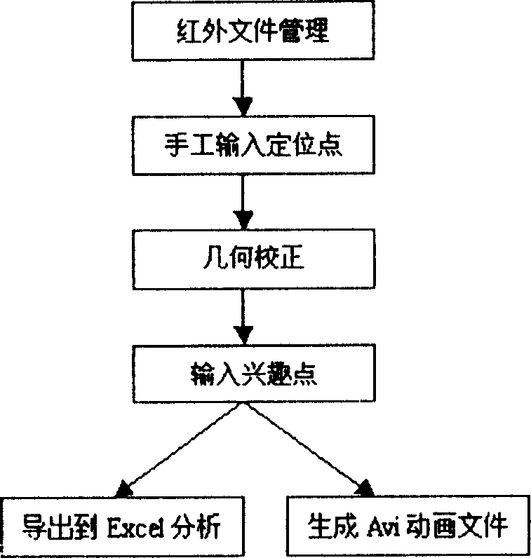
[0019] Combine the following figure 1 Illustrate the flow process of the present invention:

[0020] The applicant has implemented the infrared file management function in the infrared analysis software of the computer. The user can classify and manage the infrared thermal images taken in different periods in the analysis software, and organize the images of the equipment to be analyzed in different periods into one analysis file through this function. Secondly, through the positioning points manually input by the user, the geometric correction operation is performed on these images by using affine, projection or quadratic transformation matrix, and these images are registered according to the spatial position of the reference image. Then, the user can take advantage of the "surface scanning" of the thermal imager to search and pick points of interest on the image, and the software will automatically display the temperature change curve of the device at this spatial point in d...


PUM


Abstract

This invention relates to infrared sequence image history trend analysis method and belongs to device fault diagnose field. This invention comprises the following steps: first to collect the infrared heat images caught in different periods of the device to be measured into one analysis file fold; second to input position points by human and use artificial conversion matrix, project conversion matrix or quadrics conversion matrix; then to use double linear insert and correct the image by geometry and aligns it according to reference image space position; third to use the characteristics of side scanning of thermal imaging device to scan images to get the interest points position and temperatures and give and display the change curve in different temperature at the interest points. íí

Description

technical field [0001] The invention belongs to the field of equipment fault diagnosis, and proposes a historical trend analysis method for equipment fault diagnosis by using infrared sequence images. Background technique [0002] Infrared thermal imaging cameras and their image analysis software have been widely used in the field of infrared equipment fault diagnosis. In practice, it is mainly to measure the temperature of the equipment through the temperature measurement function of the infrared thermal imaging camera to find the thermal fault of the equipment. Compared with the contact measurement method, the thermal imager is a non-contact online detection, that is, the online non-contact temperature measurement can be carried out without stopping the equipment; What is the temperature value of all points on a projection plane; and the results it gives are intuitive, through false color enhancement, high temperature and low temperature areas can be displayed in an intuit...

Claims


Application Information

Patent Timeline
Patent Type & Authority Applications(China)
IPC IPC(8): G01J5/00G06F3/00G06K9/20
Inventor 王晓宇陈吉红彭芳瑜黄植红
Owner HUAZHONG UNIV OF SCI & TECH
Why Eureka
Try Eureka