
Patsnap Eureka
For R&D, Patsnap Eureka makes reading and utilizing patents & technical documents easy.
Patsnap Eureka AIR
Designed for self-driven R&D workflows. Generate viable solutions, solve complex R&D challenges, empower your innovation with AI.

Patsnap Eureka Materials
Designed for material experts only. Revolutionize your material R&D, from search, analyze, to developing new materials.

TechResearch
Generate reliable direction feasibility study reports for your R&D in just a few steps.

TechSeek
Discover and master advanced knowledge NOW. Basics, ideas, possibilities, all at once.

TechMind
As an expert in R&D Theories, TechMind can generates customized viable solutions instantly.

TechRisk
Analyze your overall solution with one click, know your potential R&D risks in advance.

TechMonitor
Get weekly tech updates, stay abreast of the latest tech innovations and key insights.
Historical trend analysis method for infrared sequence image
A technology of sequential images and historical trends, applied in the field of historical trend analysis, can solve problems such as low efficiency and unsatisfactory applications
- Summary
- Abstract
- Description
- Claims
- Application Information
AI Technical Summary
Problems solved by technology
Method used
Image

Examples
Embodiment Construction
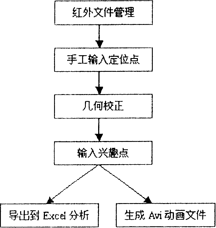
[0019] Combine the following figure 1 Describe the flow of the present invention:
[0020] The applicant has realized the infrared file management function in the infrared analysis software of the computer. The user can classify and manage the infrared thermal images taken in different periods in the analysis software, and organize the images of the equipment to be analyzed in different periods into one analysis file through this function. Secondly, through the positioning points manually input by the user, use affine, projection or quadratic transformation matrix to perform geometric correction operations on these images, and register these images according to the spatial position of the reference image. The user can then take advantage of the thermal imager's "surface scan" to search and pick points of interest on the image, and the software automatically displays a graph of the device's temperature change at this spatial point over time. Finally, the user can import the te...
PUM
 Abstract
Description
Claims
Application Information
 - R&D Engineer
- R&D Manager
- IP Professional
- Industry Leading Data Capabilities
- Powerful AI technology
- Patent DNA Extraction
Browse by: Latest US Patents, China's latest patents, Technical Efficacy Thesaurus, Application Domain, Technology Topic, Popular Technical Reports.
© 2024 PatSnap. All rights reserved.Legal|Privacy policy|Modern Slavery Act Transparency Statement|Sitemap|About US| Contact US: help@patsnap.com