Open-end type spinning machine including fiber collecting surface as well as method of spinning yarn thereof

A fiber, spinning machine technology, applied in the field of devices implementing the method, can solve the problems of reduction, loss of yarn amount, difference in rotation speed ratio, etc.

Inactive Publication Date: 2010-05-12
利特英格纺织机械制造股份公司
View PDF4 Cites 0 Cited by
  • Summary
  • Abstract
  • Description
  • Claims
  • Application Information

AI Technical Summary

Problems solved by technology

And each deceleration inevitably results in a loss of the amount of yarn produced
In addition, in terms of the quality of the yarn produced, there is also a reduction
Because of the change in speed, it can cause the difference in the speed ratio between the machines

Method used


Image

  • Open-end type spinning machine including fiber collecting surface as well as method of spinning yarn thereof
  • Open-end type spinning machine including fiber collecting surface as well as method of spinning yarn thereof
  • Open-end type spinning machine including fiber collecting surface as well as method of spinning yarn thereof

Examples


Embodiment Construction

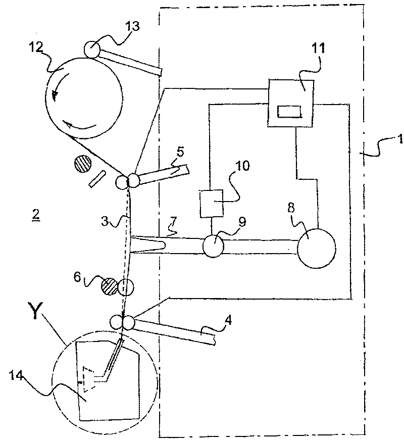
[0024] figure 1 A maintenance device 1 is schematically shown in . The maintenance device 1 is located in front of an open-end spinning machine 2 which is shown only in part. The maintenance device 1 has a first pair of auxiliary rollers 4 and a second pair of auxiliary rollers 5 for gripping the yarn 3 . Between the first and the second auxiliary roller pair 4 , 5 is a main roller pair 6 which belongs to the open-end spinning machine 2 . A yarn storage device 7 is also arranged between the two auxiliary roller pairs 4,5. The shown yarn storage device 7 consists of a vacuum source 8 , a valve 9 and a servo drive 10 . Both the vacuum source 8 and the servo drive 10 are connected to a control device 11 and are regulated by it. Also connected to the control device 11 are the above-mentioned two pairs of auxiliary rollers 4 and 5 . In the shown state, the bobbin 12 on which the yarn 3 is wound on the open-end spinning machine 2 is driven by an auxiliary drive 13 of the mainte...


PUM


Abstract

The present invention relates to a method for beginning to spin the yarn (3) and is used on an open port-type fine spinning machine (2) which comprises a fiber gathering surface, wherein, one yarn end(15) of the spinning yarn (3) is sent to a function area of the sucking air current which flows into the open port-type fine spinning machine (2) and is held therein after forming a yarn surplus segment, subsequently the yarn (3) is loosened and is conveyed to the fiber gathering surface with unloosening the yarn surplus segment. Therefrom the yarn (3) combines with the fiber provided from the fiber gathering surface and is resumed with pulling. The method is characterized in that the yarn surplus segment is composed by a constant-invariable first yarn length and is pulled rearwards in a yarnstorage device (7). The back pulling is released at the first time point. At a second time point the yarn (3) is loosened to send the yarn (3) into the open port-type fine spinning machine (2) and atthe third time point the preset yarn length conveying is adjusted to a necessary and variable second yarn length, wherein the three time points coordinate with one another and facilitates that the conveying process adjusted to the second yarn length starts from the third time point and finishes when the yarn storing in the yarn storing device runs out at latest.

Description

technical field [0001] The invention relates to a method for starting spinning of a yarn used in an open-end spinning machine having a fiber collecting surface, and to a device for carrying out the method. [0002] In this method, an end of the spun yarn is conveyed into the active area of ​​the suction air flow and held there by means of two pairs of auxiliary rollers forming a surplus section of the yarn, which The air flow flows into the open-end spinning machine. Next, the yarn is loosened and conveyed by the loosening of the surplus yarn to the fiber collecting surface, from where the yarn is combined with the fibers conveyed by the fiber collecting surface and then drawn. Background technique [0003] In modern open-end spinning machines, it is often necessary to reconnect the yarn or start spinning for various reasons. For example, when the yarn breaks, or when respinning with an empty spool. As a result, machinery operators are constantly pursuing the economy of m...

Claims


Application Information

Patent Timeline
Patent Type & Authority Patents(China)
IPC IPC(8): D01H4/48
Inventor F·拜尔
Owner 利特英格纺织机械制造股份公司
Why Eureka
Try Eureka