Eureka AIR delivers breakthrough ideas for toughest innovation challenges, trusted by R&D personnel around the world.

Map display apparatus

A map display device and map technology, which are applied in measurement devices, image data processing, 3D image processing and other directions, can solve problems such as difficulties, and achieve the effect of preventing jaggies and having high practical value.

Inactive Publication Date: 2005-05-18
GK BRIDGE 1
View PDF1 Cites 16 Cited by
  • Summary
  • Abstract
  • Description
  • Claims
  • Application Information

AI Technical Summary

Problems solved by technology

Therefore, it is difficult to apply these countermeasures to devices such as navigation devices with less hardware resources in the current situation

Method used


Image

  • Map display apparatus
  • Map display apparatus
  • Map display apparatus

Examples


Embodiment approach 1

[0041] Image 6 It is a block diagram showing part of the configuration of the map display device according to Embodiment 1 of the present invention.

[0042] This map display device is a device that generates a three-dimensional image from digitized map data and displays the map on a screen, and includes a map data storage unit 101 that stores map data such as position information and altitude information of objects displayed on the screen. Obtain the map data from the map data storage unit 101, and generate the map drawing data generating unit 102 of the map drawing data such as the shape data of the object; the map drawing data generated in the above-mentioned map data generating unit is subjected to drawing processing, and generate and display on the screen The rendering unit 103 of the image in the image; the display unit 104 that displays the image generated by the rendering unit 103 on a real screen such as a monitor.

[0043] The map data storage unit 101 stores longi...

Embodiment approach 2

[0073] In this embodiment, a case will be described in which whether to perform correction and display for each building is determined based on a display correction flag included in map data. The structure of this embodiment is the same as that of Embodiment 1. Image 6 Descriptions are made, and descriptions of the same parts are omitted.

[0074] In this embodiment, the three-dimensional building data stored in the map data storage unit 101 and the operation of the model-view conversion matrix changing unit 102d are different from the first embodiment. Other points are the same as those in Embodiment 1.

[0075] In the map data storage unit 101, the height H of the building as a three-dimensional object, the number N of vertices N of the polygonal prism shape constituting the bounding rectangle of the building, the coordinates Pi (i=1 to N) of each vertex, attributes, etc. , further storing 3D building data with a display correction flag indicating whether to change the mo...


PUM


Abstract

The map display device of the present invention includes: a model-view transformation matrix generating unit (102c) for generating a model-view transformation matrix of 4 rows and 4 columns for converting the global coordinates of a 3-dimensional object into a viewpoint coordinate system; a model-view transformation matrix changing unit (102d), when performing coordinate transformation by multiplying the model-view transformation matrix from the left side of the coordinates, change the value of the first row, the second column, and the third row, the second column of the model-view transformation matrix to 0, and On the one hand, when performing coordinate conversion by multiplying the model-view transformation matrix from the right side of the coordinates, change the value of the 2nd row, 1st column and the 2nd row, 3rd column of the model-view transformation matrix to 0; the model view The conversion unit (102e) converts the global coordinates into the viewpoint coordinate system using the changed model-view conversion matrix.

Description

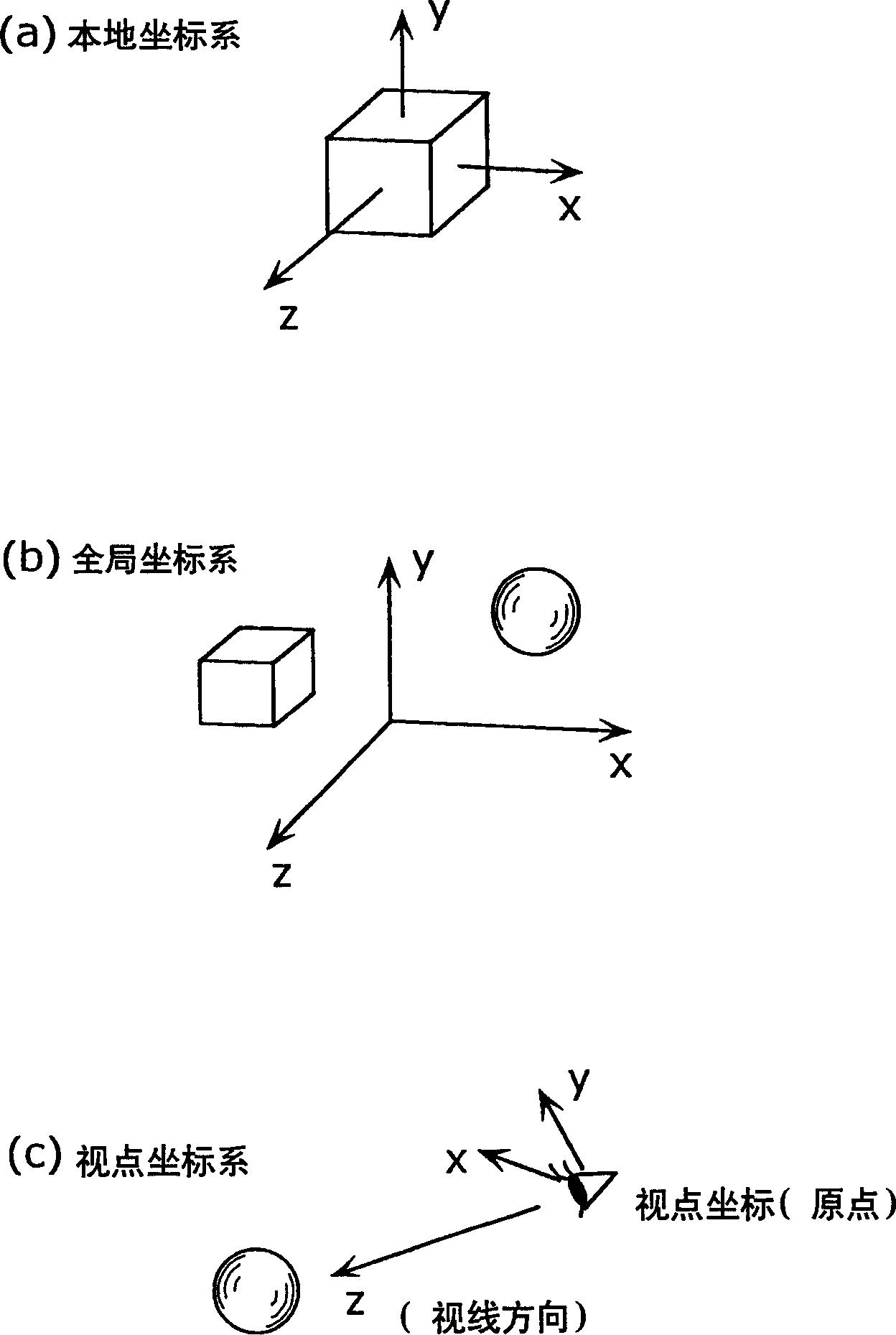
technical field [0001] The present invention relates to a map display device for displaying a map on a screen, and more particularly to a map display device for generating a three-dimensional image from digitized map data and displaying a map on a screen. Background technique [0002] Conventionally, a map display device that generates and displays a 3D image from a digitized map has been used, for example, in a navigation device or map display software for a personal computer (see, for example, Japanese Patent Application Laid-Open No. 9-281889). [0003] In such a map display device, three-dimensional coordinates are converted into two-dimensional coordinates in order to display objects such as buildings and viaducts defined in a three-dimensional space on a two-dimensional screen. Here, the center of each 3D object is taken as the origin figure 1 The coordinate system shown in (a) is called the "local coordinate system"; the figure 1 The coordinate space shown in (b) is...

Claims


Application Information

Patent Timeline
Patent Type & Authority Applications(China)
IPC IPC(8): G01C21/36
CPCG01C21/3638
Inventor 吉田直史荒木均仙田圭一汤田正人川崎刚照
Owner GK BRIDGE 1
Why Eureka
Eureka Blog
Learn More