
Rotary compressor

A rotary compressor and compression chamber technology, applied in the field of compressors, can solve problems such as application degree limitation, and achieve the effect of saving electricity and increasing costs

Inactive Publication Date: 2005-05-04
LG ELECTRONICS (TIANJIN) APPLIANCES CO LTD
View PDF0 Cites 4 Cited by
  • Summary
  • Abstract
  • Description
  • Claims
  • Application Information

AI Technical Summary

Problems solved by technology

However, the traditional rotary compressor only has one compression capacity, so its application is considerably limited.

Method used


Image

  • Rotary compressor
  • Rotary compressor
  • Rotary compressor

Examples


Embodiment Construction

[0038] Below, various embodiments of the rotary compressor of the present invention will be described in detail with reference to the accompanying drawings.

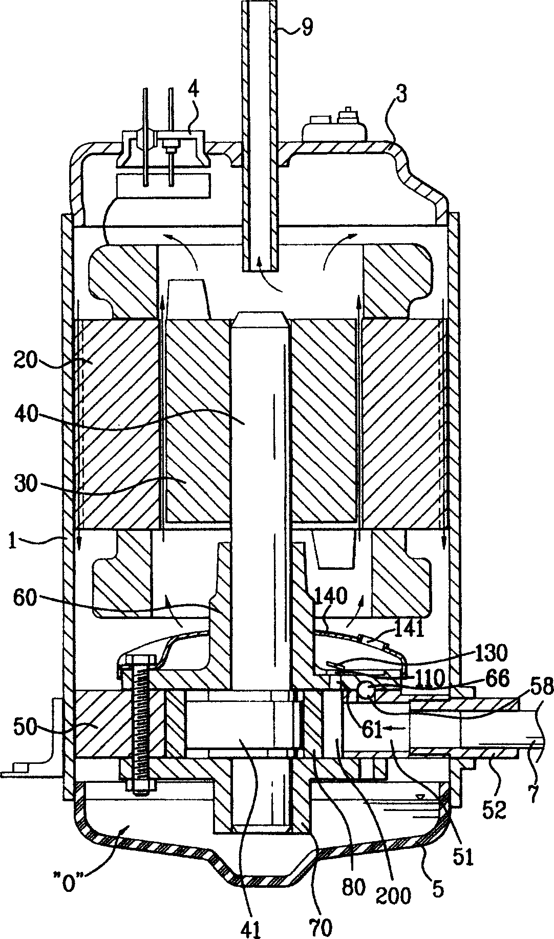
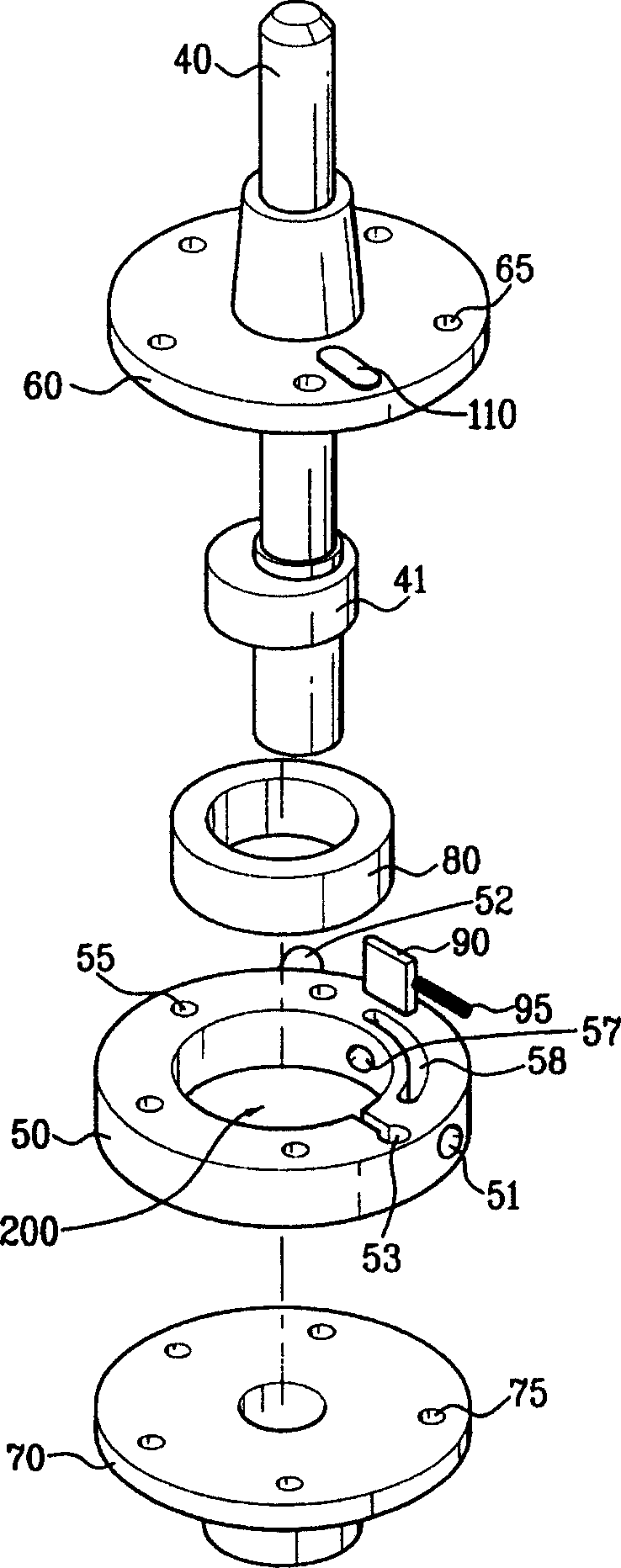
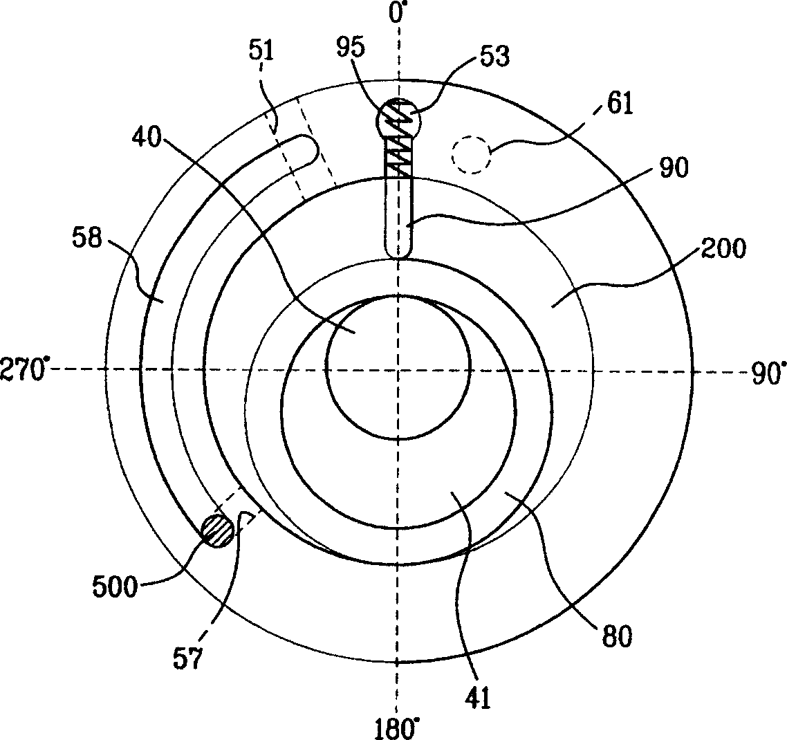
[0039] figure 1 It is a structural schematic diagram of important parts of an embodiment of the rotary compressor of the present invention; figure 2 Yes figure 1 The exploded schematic diagram of the compression part of the rotary compressor in ; image 3 Yes figure 1 A schematic plan view of the compression part of the rotary compressor in ; Figure 4 Yes figure 1 The schematic diagram of the bottom surface of the upper bearing in the rotary compressor of ; Figure 5a to Figure 5c Yes figure 1 , a schematic diagram illustrating the sequence of the compression process in the maximum power mode; Figure 6a to Figure 6c Yes figure 1 , Schematic illustration of the sequence of the compression process in sub-power mode.

[0040] First, if figure 1 , figure 2 As shown, the rotary compressor of the present inventi...


PUM


Abstract

The invention discloses a rotary compressor which includes the casing, the electromotion part and the compression part. The electromotion part locates on the top of the casing; the compression part which includes cylinder, rolling hoop, top axletree and lower axletree locates inside and on the bottom of the casing; there is compression cavity with some cubage in the cylinder; the sucking hole communicates with the compression cavity; the bypass opening locates the place which is some distance away the sucking hole; the discharge hole discharges the compressed gas from the compression cavity. The rolling hoop eccentrically connects with the rotation axis, rolls on the inner surface of the compression cavity and divides the space which is used for sucking and compression together with the inner surface. The spacing block is set between the sucking hole and the discharge hole, maintains spring contact with the rolling hoop and divides the compression cavity into sucking space and the discharge space. The makeandbreak unit selects and opens or closes the by-pass port according to compression module. The invention can get double compression energy by a compressor, provide adequate compression energy corresponding to the run condition realizes double compression energy and saves electric power.

Description

technical field [0001] The present invention relates to a compressor. In particular, it relates to a rotary compressor that can obtain two different compression capacities in a compression mode when rotating in one direction. Background technique [0002] Generally, a compressor is a machine that uses the power of a motor or a steam turbine to pressurize working fluids such as air and refrigerant to increase the pressure of the working fluid. This kind of compressor is widely used in the fields of home appliances such as air conditioners and refrigerators, as well as in production fields. [0003] According to the type of compression, compressors can be divided into volumetric compressors and turbo compressors. [0004] Among them, the volumetric compressor is widely used in the production field. The compression method of the volumetric compressor is to increase the pressure by reducing the volume. Volumetric compressors can be classified into reciprocating compressors a...

Claims


Application Information

Patent Timeline
IPC IPC(8): F04C18/356
Inventor 盧铁基金宗奉朴京俊張昌镛裵志英高英煥
Owner LG ELECTRONICS (TIANJIN) APPLIANCES CO LTD
Learn More