
Ink-jet recording head substrate, ink-jet recording head, and ink-jet recording apparatus

A technology of inkjet recording and substrate, which is applied in the field of inkjet recording head and inkjet recording device, inkjet recording head substrate, and can solve the problems of substrate size increase and so on

Inactive Publication Date: 2005-05-04
CANON KK
View PDF2 Cites 1 Cited by
  • Summary
  • Abstract
  • Description
  • Claims
  • Application Information

AI Technical Summary

Problems solved by technology

Therefore, if the number of heat generating elements driven at a time is doubled, the width of the wire increases by three to four times, so that there is a problem of a rapid increase in the size of the substrate

Method used


Image

  • Ink-jet recording head substrate, ink-jet recording head, and ink-jet recording apparatus
  • Ink-jet recording head substrate, ink-jet recording head, and ink-jet recording apparatus
  • Ink-jet recording head substrate, ink-jet recording head, and ink-jet recording apparatus

Examples


Embodiment Construction

[0022] Embodiments of the present invention will be described with reference to the following drawings.

[0023] Figure 4A and Figure 4B is a perspective view illustrating a recording head cartridge 1000 having a recording head 1001 according to an embodiment of the present invention.

[0024] The recording head cartridge 1000 is composed of a recording head 1001 (ink jet recording head), and an ink container 1900 (ink containers 1901, 1902, 1903, and 1904) provided in the recording head 1001 in a detachable manner. The recording head 1001 ejects the ink supplied from the ink container 1900 through the ink outlet according to the recording information.

[0025] The recording head cartridge 1000 is detachably fixed to a carriage (not shown) located on the body of the ink jet recording apparatus by positioning means and electrical contacts.

[0026] For example, the recording head 1001 can be an inkjet recording head of a recording system that uses a heat generating body to...


PUM


Abstract

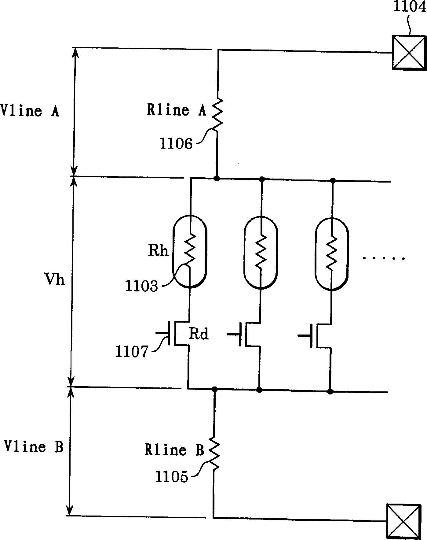
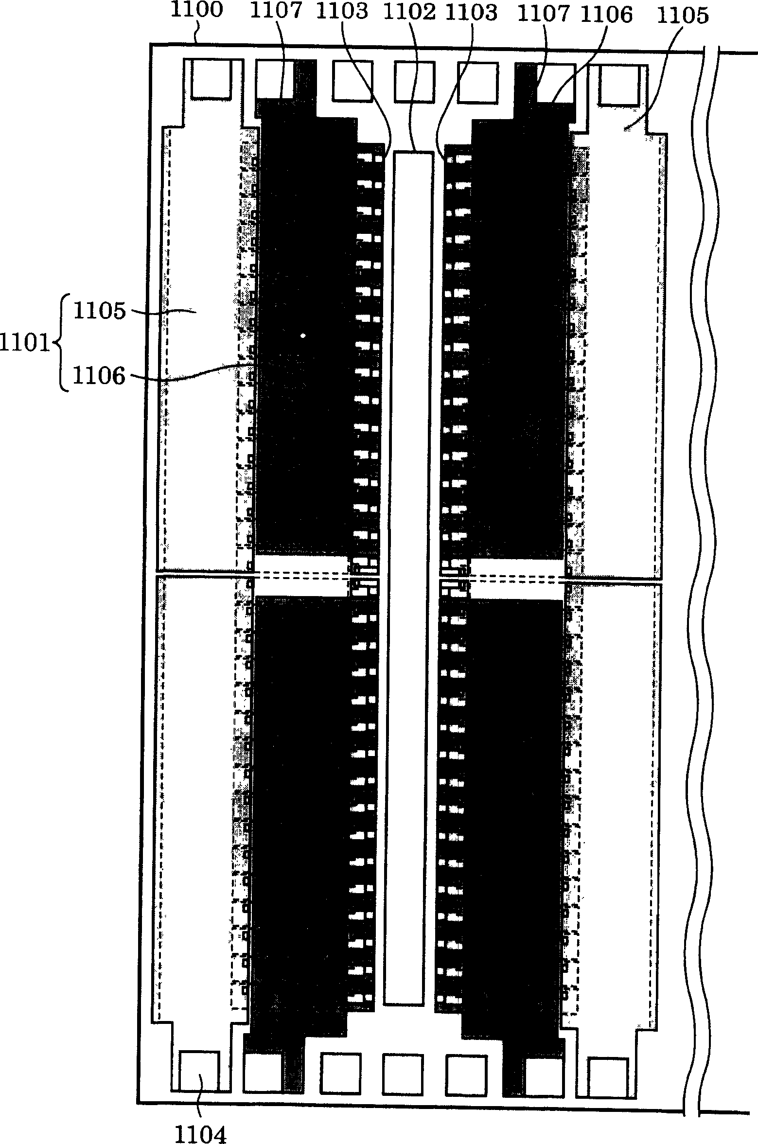
A recording head substrate allowing an increased number of the exothermic bodies driven at a time without increasing the substrate size so as to increase a number of nozzles arranged in high density. The recording head substrate includes a plurality of electrothermal conversion members having exothermic bodies respectively corresponding to a plurality of discharge ports; a plurality of drive elements for driving the exothermic bodies; common wiring A connected to the exothermic bodies; and common wiring B connected to the drive elements; and an electrode pad connected to the common wiring A and the common wiring B. A number of the exothermic bodies driven at a time is determined by (RlineA+RlineB) / (Rh+Rd)<0.05 / (0.95 n-1).

Description

technical field [0001] The present invention relates to an inkjet recording head substrate, an inkjet recording head, and an inkjet recording device. Background technique [0002] In an ink jet recording head, in order to eject various ink droplets from one substrate, a plurality of ink supply ports are provided on one substrate. Furthermore, in order to improve the performance of cleaning ink accumulated on the orifice plate of a substrate, the substrates are connected by providing electrode pieces arranged on the peripheral edge of the substrate parallel to the shorter side of the groove of each ink supply port. to an external instrument. In this structure, since the distance between the heat generating body and the electrode sheet differs depending on the position of each heat generating body, the heat generating body farther from the electrode sheet tends to have a larger wiring resistance. Therefore, when a plurality of heating elements connected to a section of wire ...

Claims


Application Information

Patent Timeline
Patent Type & Authority Applications(China)
IPC IPC(8): B41J2/05B41J2/14
CPCB41J2/0458B41J2/14072B41J2/04541B41J2/04543
Inventor 初井琢也尾崎照夫今仲良行伊部智
Owner CANON KK
Learn More