
Spinning reel sounding mechanism

一种绕线轮、构件的技术,应用在钓鱼用绕线轮、捕鱼、应用等方向,能够解决不能获得清脆的声音、妨碍卷筒平稳转动等问题

Inactive Publication Date: 2005-05-04
SHIMANO INC
View PDF2 Cites 9 Cited by
  • Summary
  • Abstract
  • Description
  • Claims
  • Application Information

AI Technical Summary

Problems solved by technology

Large fluctuations in rotational torque will prevent smooth roll rotation
On the other hand, if the pressing force of the spring member is reduced to ensure smooth rotation of the reel, crisp sound cannot be obtained

Method used


Image

  • Spinning reel sounding mechanism
  • Spinning reel sounding mechanism
  • Spinning reel sounding mechanism

Examples


Embodiment Construction

[0048] Selected embodiments of the present invention will now be described with reference to the drawings. It will be understood by those skilled in the art from this specification that the following description of the embodiments of the present invention is for illustrative purposes only, and is not intended to limit the present invention. The present invention is defined by the appended claims and their equivalents.

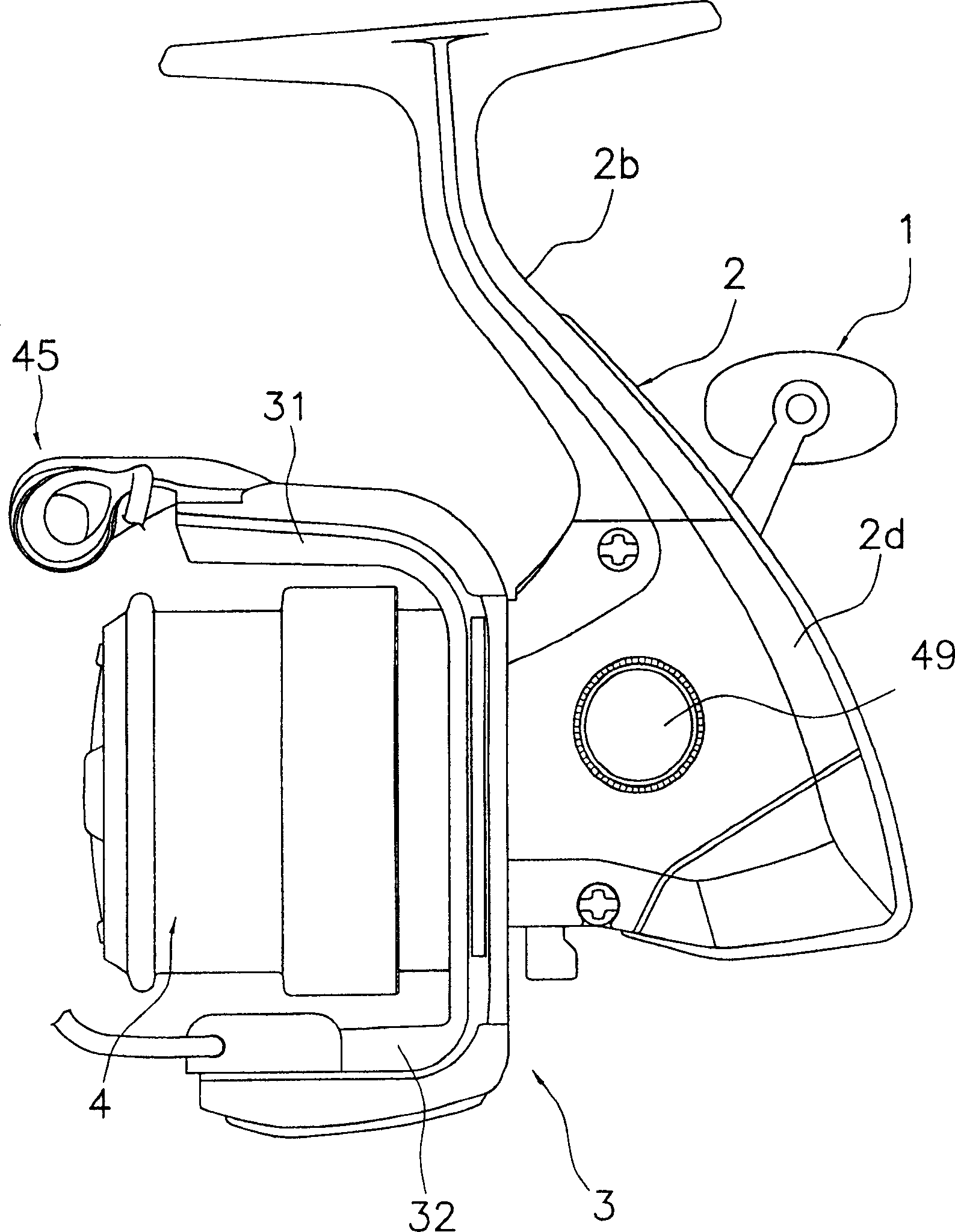
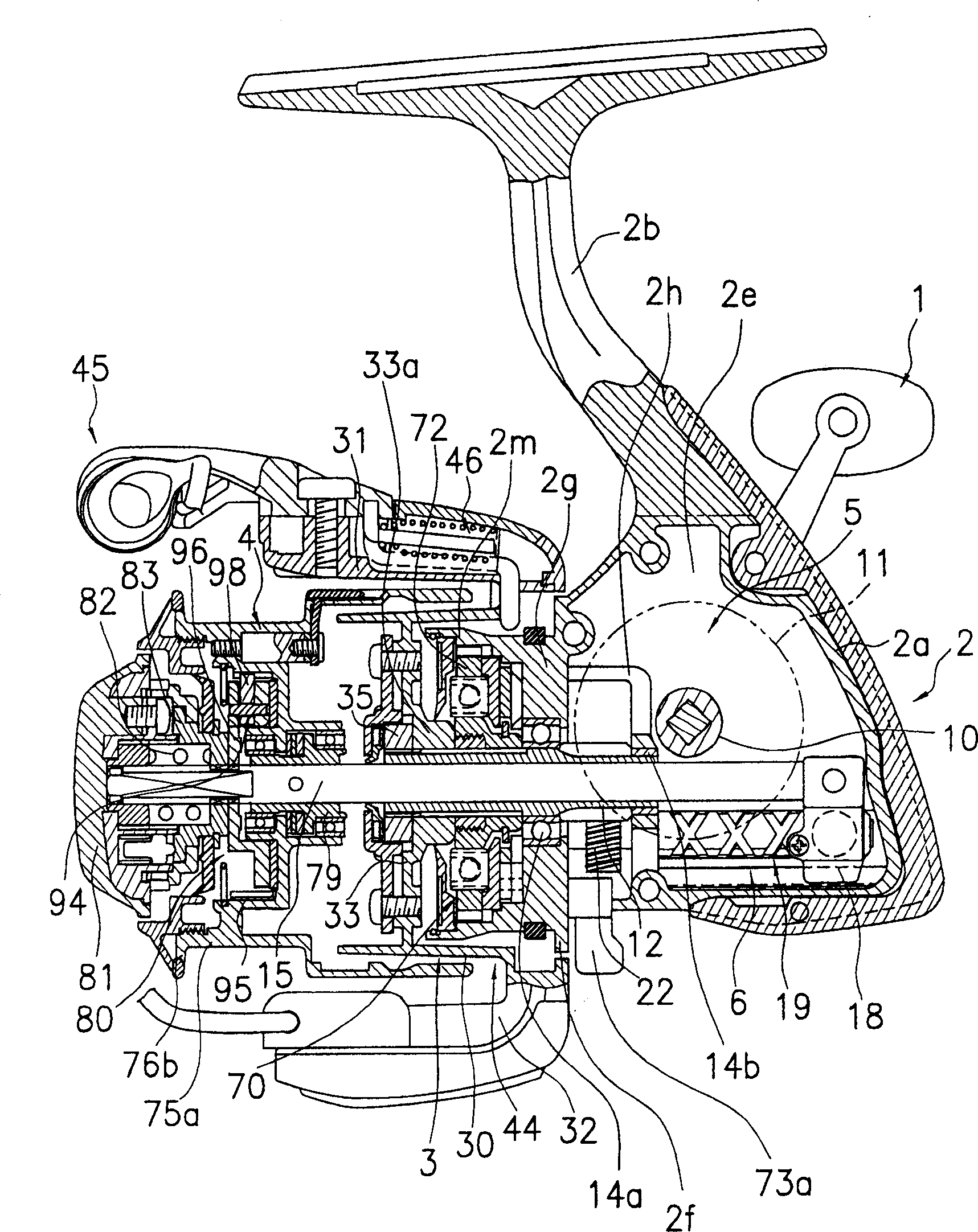
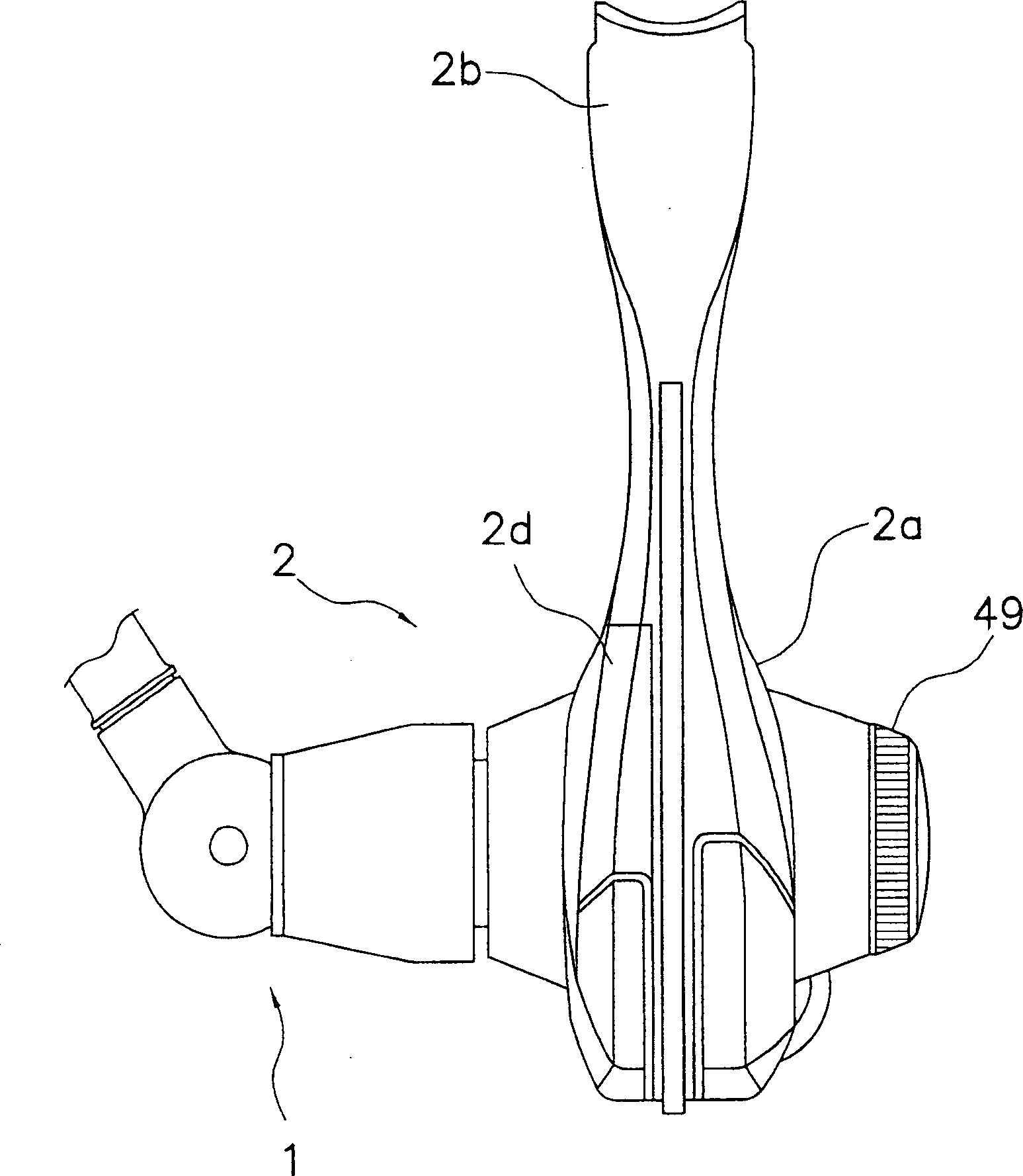
[0049] Such as figure 1 with 2 As shown, the rotating reel according to the embodiment of the present invention is adopted, including a handle 1, a reel unit 2 rotatably supporting the handle 1, a rotor 3, and a reel 4. The rotor 3 is rotatably supported on the front part of the reel unit 2. The reel 4 makes the fishing line wind around its outer peripheral surface and is arranged on the front of the rotor 3 so that the reel 4 can move back and forth. Noticed as figure 1 with 2 As shown, the crank 1 is installed on the right side, and the crank cover 49 is instal...


PUM


Abstract

A second sounding mechanism includes a first member, a plurality of concave / convex portions that are formed on an inner peripheral surface of the first member to be spaced apart in the circumferential direction, a second member that is non-rotatably mounted on a spool shaft, a pawl member that is arranged on the second member to be pivotable and contactable with the concave / convex portions, and a pair of urging members that are arranged on both sides of the pawl member and urge the pawl member to a central position by pressing on both sides thereof. The tip of the pawl member is arranged to be contactable with the concave / convex portions, and the concave / convex portions repeatedly contact with the pawl member to produce sounds when the spool is rotated. In a sounding mechanism of a spinning reel, the spool can rotate smoothly, while clear, crisp sounds can be obtained.

Description

Technical field [0001] The present invention generally relates to a sounding mechanism of a rotating reel. The present invention particularly relates to a sound mechanism of a rotating reel that generates sound through relative movement between a reel for winding and releasing fishing line and a reel shaft. Background technique [0002] The rotating reel generally includes a reel unit rotatably supporting the crank, a rotor, and a reel rotatably mounted on the reel shaft. The reel of the rotating reel moves back and forth with respect to the reel unit, and includes a cylindrical portion with fishing line wound on its outer periphery and a large-diameter skirt portion provided at the rear end of the cylindrical portion. A reel mount that restricts the backward movement of the reel is provided at the rear end of the barrel portion. The inside of the barrel portion of the front resistance type rotating reel includes a resistance mechanism having a plurality of resistance plates and ...

Claims


Application Information

Patent Timeline
Patent Type & Authority Applications(China)
IPC IPC(8): A01K89/01
CPCA01K89/01
Inventor 生田刚
Owner SHIMANO INC
Learn More