
Latch with switch

A switch and card lock technology, applied in the field of card locks, can solve the problems of high cost, high price and high price of card locks, and achieve the effects of ensuring reliability, easy assembly and good workability

Inactive Publication Date: 2005-04-27
NIFCO INC
View PDF1 Cites 6 Cited by
  • Summary
  • Abstract
  • Description
  • Claims
  • Application Information

AI Technical Summary

Problems solved by technology

[0004] Since the movable terminal is manufactured by cutting and bending a thin metal plate, it is expensive (high cost)
[0005] Therefore, the price of a card lock with a switch is high

Method used


Image

  • Latch with switch
  • Latch with switch
  • Latch with switch

Examples


Embodiment Construction

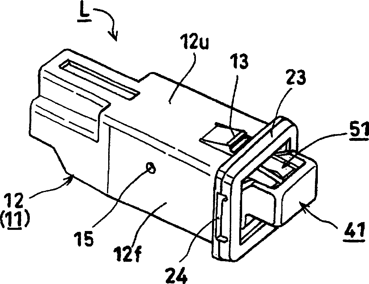
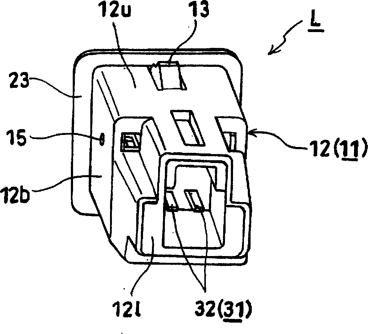
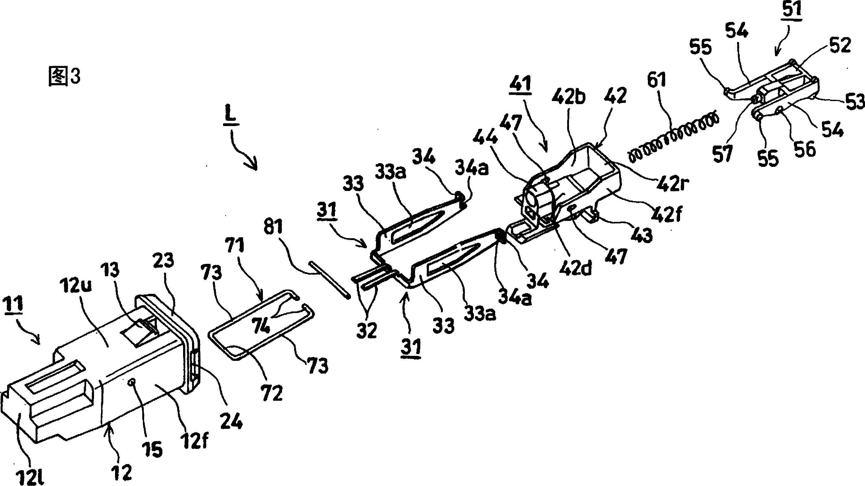
[0045] figure 1 It is a front perspective view of the latch with switch according to the first embodiment of the present invention, figure 2 yes figure 1 Figure 3 is a perspective view from the back of the shown latch with switch figure 1 and figure 2 An exploded perspective view of the latch with switch shown.

[0046] In these figures, L represents a latch with a switch, which is composed of the following parts: a box-shaped housing 11 with one side (right side) open, a pair of fixed terminals 31 fixed in the housing 11, and a pair of fixed terminals 31 to the housing. The movable part 41 inserted in the body 11, the locking part 51 that is rotatably installed on the movable part 41, is packed between the locking part 51 and the housing 11, and the movable part 41 is moved toward the body by means of the locking part 51. The helical spring 61 as the biasing member that energizes from the direction that housing 11 protrudes, the guide rod 71 that is installed on the hou...


PUM


Abstract

Provided is a latch with a switch enabling a movable terminal to be easily attached. This latch with a switch is so structured that, when a movable terminal 41 is pushed into a housing 11 against energizing force of a coil spring, the movable member is locked at the pushed-in position by a lock mechanism to turn on the switch; and when the movable member is pushed into the housing against the energizing force of the coil spring again, the lock mechanism is brought into an unlocking state to restore the movable member to a projected position by the energizing force of the coil spring. The switch is composed of: a pin 81 attached to the movable member and having both ends projecting from two facing side faces of the movable member; and a pair of fixed terminals 31 fixed to the facing inner side faces of the housing, brought into a conducting state by bringing both the ends of the pin into contact with them when the movable member is in the projected position, and brought into a non-conducting state by separating both the ends of the pin from them when the movable member is in the pushed-in position. The pin is incorporated from a movable terminal insertion hole 15 formed in the side faces of the housing.

Description

technical field [0001] The present invention relates to a belt for providing a switch, for example, on a switch part for pressing to close a door of a cassette recorder, etc., pressing and opening the closed switch part again, or on a latch mounted on a mounted part such as a main body. The latch of the switch. Background technique [0002] The structure of the conventional latch with switch is that it has a movable part that urges a part of the protruding position protruding from the casing with the urging part, and pushes the movable part into the casing by resisting the urging force of the urging part. The double-push locking mechanism is in a locked state, so that the movable part is locked in the pushed position, and the switch is turned on at the same time; the movable part in the pushed position is pushed into the housing by resisting the force of the force-applying part. The locking mechanism is in an unlocked state, and the active part is reset to the protruding po...

Claims


Application Information

Patent Timeline
Patent Type & Authority Applications(China)
IPC IPC(8): E05C3/24E05B27/00E05C19/02H01H3/42H01H13/56
CPCH01H13/562H01H27/00E05C3/24E05B27/00E05C19/02
Inventor 一丸贵秀
Owner NIFCO INC
Learn More