Image quality correction apparatus and image quality correction method

A technology of image quality and correction amount, applied in the field of image quality correction devices, can solve problems such as subtitle image quality difference, inability to generate input image correction, image quality deterioration and the like

Inactive Publication Date: 2005-03-16
PANASONIC CORP
View PDF1 Cites 5 Cited by
  • Summary
  • Abstract
  • Description
  • Claims
  • Application Information

AI Technical Summary

Problems solved by technology

[0016] However, in the above-mentioned conventional structure, when there is a character input area in the input image, such as subtitles of a movie, although only the image data of the image area except the character area is intended to be corrected, Even the brightness value of the text has been counted when the brightness histogram is generated
Therefore, it is impossible to generate a luminance histogram of only the image area in the input image, and since the correct correction amount cannot be calculated, there is a problem that the optimal correction cannot be performed for the generated input image.
[0017] In addition, there is the following problem in devices that can select the presence or absence of subtitles (with or without subtitles) like a DVD player: because the shape of the luminance histogram changes due to the presence or absence of subtitles, even the same scene will vary depending on whether the subtitles are present or not. The difference in image quality due to the presence or absence of subtitles
[0018] In addition, the text area included in the image is often set with a brightness value that is very different from the image area in order to make the text easy to see. This appears as an extreme shape in the brightness histogram, so there is the following problem: When the correction amount is calculated based on the luminance histogram, incorrect correction is performed when performing image quality correction, and the image quality deteriorates due to the correction

Method used


Image

  • Image quality correction apparatus and image quality correction method
  • Image quality correction apparatus and image quality correction method
  • Image quality correction apparatus and image quality correction method

Examples


Embodiment approach 1

[0079] Hereinafter, an image quality correction device and an image quality correction method according to Embodiment 1 of the present invention will be described with reference to the drawings.

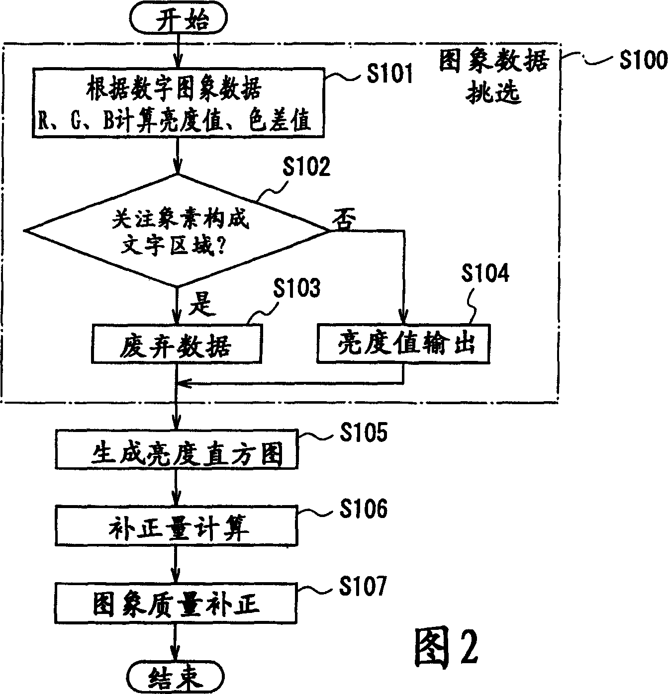
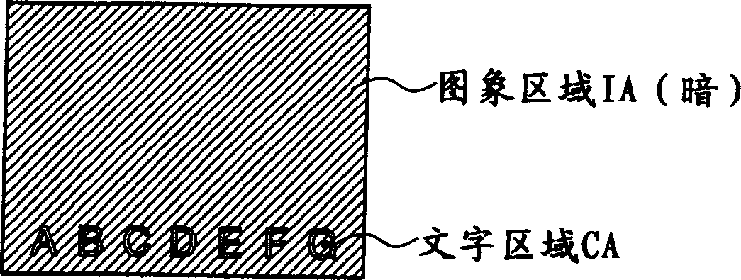
[0080] The image quality correction device and image quality correction method according to Embodiment 1 of the present invention generate a luminance histogram of an image region except a character region from input image data, and use only the generated image region A method of performing image quality correction processing on brightness histograms. Also, the character area is a data area constituting characters and the like included in an input image like subtitles of a movie, and is assumed to be a data area that appears as an extreme shape when generating a luminance histogram.

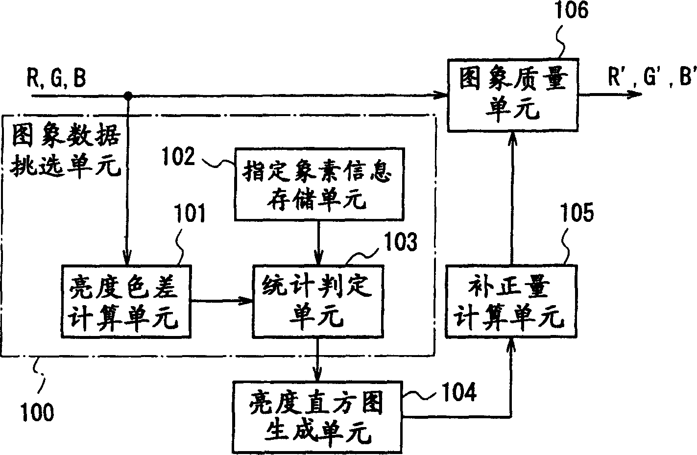
[0081] figure 1 It is a block diagram showing an example of the configuration of the image quality correction device according to Embodiment 1 of the present invention.

[0082] Such as figure 1 As...

Embodiment approach 2

[0123] Hereinafter, an image quality correction device and an image quality correction method according to Embodiment 2 of the present invention will be described with reference to the drawings.

[0124] The image quality correction device and image quality correction method according to Embodiment 2 of the present invention generate a luminance histogram from input image data, and when there is a prominent gradation in the generated luminance histogram, the detected The obtained luminance value with gradation differs from the image quality correction device and image quality correction method of Embodiment 1 in that the luminance value and the color difference value of the pixels determined to constitute the character area are obtained.

[0125] Image 6 It is a block diagram showing an example of the configuration of an image quality correction device according to Embodiment 2 of the present invention.

[0126] Such as Image 6 As shown, the composition of the image qualit...

Embodiment approach 3

[0167] Hereinafter, a modified example of the processing of the pixel information setting section 604 described in the above-mentioned second embodiment will be described as the third embodiment of the present invention.

[0168] In the pixel information setting section 604 of Embodiment 3 of the present invention, the color difference value detection section 609 of the pixel information setting section 604 described in the above Embodiment 2 is as follows: Figure 11 As shown, the color difference histogram plane generated in the color difference histogram plane generating unit 608 is divided at predetermined intervals, and it is judged whether the representative value calculated from the color difference value frequency in the divided area DA is above a predetermined threshold value, A color difference value in the divided region having a representative value equal to or greater than a predetermined threshold is detected. Furthermore, the predetermined intervals for dividing...


PUM


Abstract

A count judgement unit judges whether or not a luminous value and color-difference values calculated by a luminous color-difference calculation unit are those of a pixel as a component of a character area, and outputs only luminous values of pixels other than pixels as components of the character area, to a luminous histogram formation unit. Then, a correction amount calculation unit and an image quality correction unit perform correction of image quality of input image data on the basis of the luminous histogram that is formed by the luminous histogram formation unit using the luminous values outputted from the count judgement unit. Therefore, even when information that adversely affects image quality correction, such as characters, is mixed in the input image, appropriate correction can be performed on only the image area to be corrected.

Description

technical field [0001] The present invention relates to an image quality correcting device and an image quality correcting method, in particular to an image correcting device and an image correcting method for automatically correcting the gradation of an input image in a digital image processing device. Background technique [0002] Conventionally, as a technique for correcting an image, for example, the method disclosed in Patent Document 1 is well known. This method calculates the luminance value of each pixel of the input image, generates a luminance histogram representing the sum of pixels with the same luminance value, and performs correction processing such that the shape of the generated luminance histogram is optimal for all pixels . [0003] The conventional example disclosed in this Patent Document 1 will be described with reference to FIG. 15 . [0004] As shown in FIG. 15, the conventional image quality correction circuit is composed of an imaging element 1401,...

Claims


Application Information

Patent Timeline
Patent Type & Authority Applications(China)
IPC IPC(8): G06T5/40G06T1/00G06V30/10H04N1/40H04N1/407H04N1/46H04N1/60H04N5/20H04N5/243
CPCG06T5/40G06K2209/01G06K9/4647G06T2207/10024G06K9/4652G06K9/325G06T5/009G06V20/62G06V30/10G06V30/18095G06V30/18105G06T5/92
Inventor 丸冈和贵
Owner PANASONIC CORP
Why Eureka
Try Eureka