Vibration isolating handle
A handle and vibration isolation technology, used in vibration suppression adjustment, lightweight impact tools, control components, etc., can solve the problem of not being able to obtain vibration reduction effects, and achieve the effect of reducing vibration
- Summary
- Abstract
- Description
- Claims
- Application Information
AI Technical Summary
Problems solved by technology
Method used
Image
Examples
no. 1 example
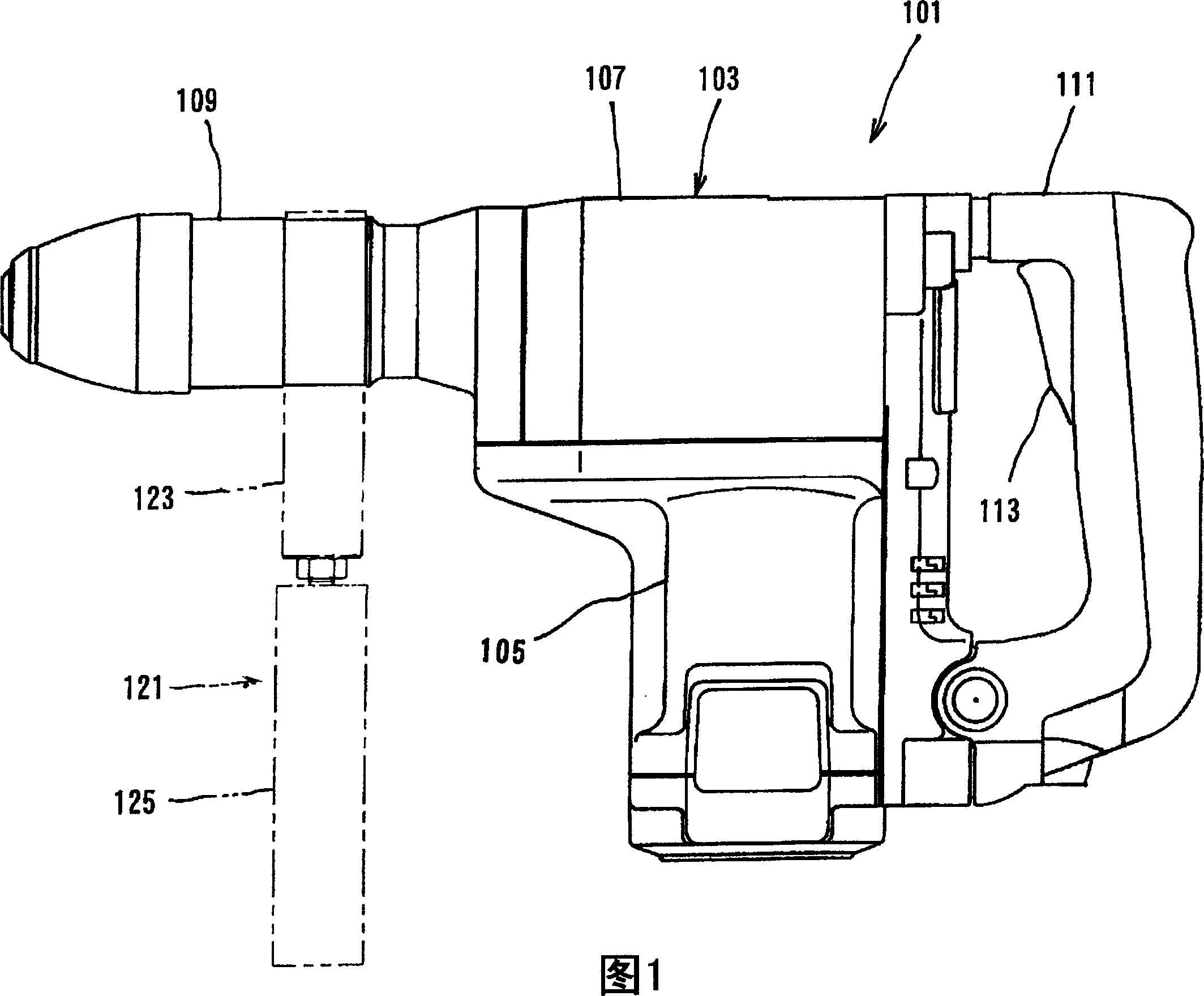
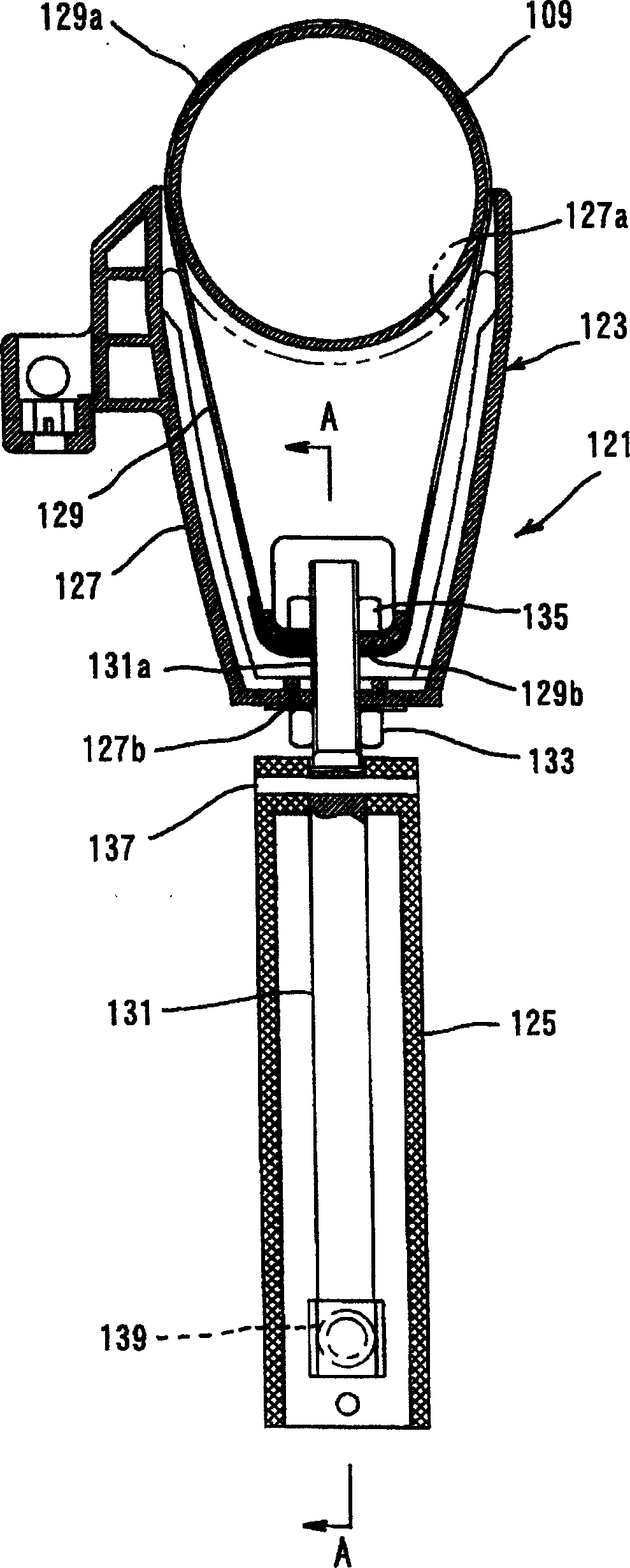
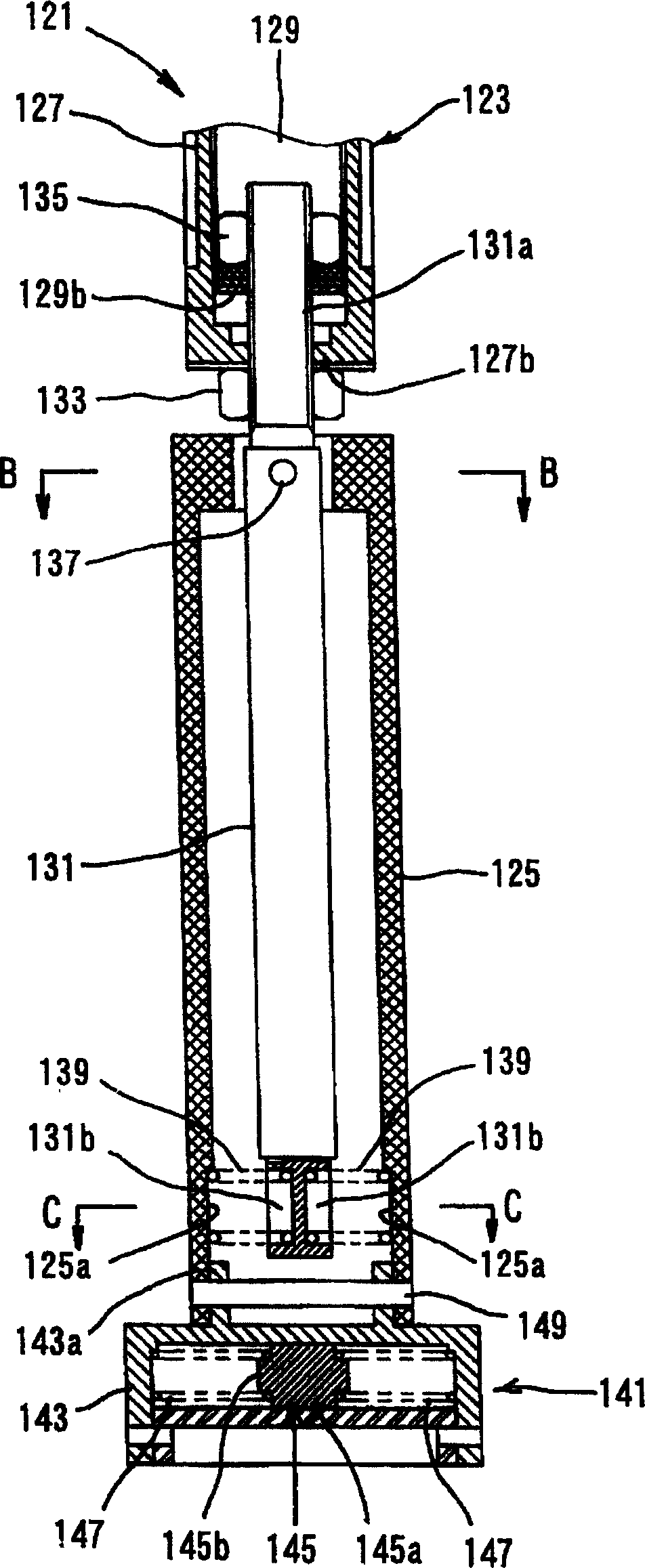
[0049] Embodiments of the present invention will be described below with reference to the accompanying drawings. Embodiments of the present invention will be explained as a vibration-isolated handle when used as an auxiliary handle to operate a rotary hammer, which is a typical example of a reciprocating power tool. Figure 1 shows the entire vibration-isolated handle attached to the hammer in dotted lines. figure 2 and image 3 is a vertical section view showing the secondary handle. also, Figure 4 and Figure 5 is a cross-sectional view showing part of the auxiliary handle.
[0050] First, the electric hammer 101 to which the auxiliary handle 121 is connected is briefly described with reference to FIG. 1 . The electric hammer 101 mainly includes a body 103 , which defines the shape of the electric hammer 101 . The body 103 is a feature corresponding to the "power tool body" of the present invention. The body 103 includes a motor housing 105 , a gear housing 107 and a ...
no. 2 example
[0076] The following will refer to Figure 6 to Figure 11 A second representative embodiment of the present invention will be described. Figure 6 shows by dotted lines the entire auxiliary handle attached to the rotary hammer. Figure 7 and Figure 8 is a vertical section view showing the auxiliary handle. also, Figure 9 to Figure 11 A cross-sectional view showing part of the auxiliary handle.
[0077] The electric hammer 201 mainly includes a body 203 , which defines the shape of the electric hammer 201 . This body 203 is a feature corresponding to the "power tool body" according to the present invention. The body 203 includes a motor housing 205 , a gear housing 207 and a tool holder (tubular portion) 209 occupying the top (front end) region of the gear housing 207 . The main handle (grip) 211 is mounted on the rear ends of the motor casing 205 and the gear casing 207 .
[0078] The auxiliary handle 221 includes a handle body 223 and a grip portion 225 . The handle ...
no. 3 example
[0093] The following will refer to Figure 12 to Figure 16 A third representative embodiment of the present invention will be described. This embodiment is a modification of the installation structure of the dynamic damper 341 of the auxiliary handle 321 according to the second embodiment. In the third embodiment, the dynamic damper 341 is constructed by using an area of about half of the side of the grip portion 325 away from the pivot shaft 337 in its longitudinal direction. The weight 345 of the dynamic shock absorber 341 extends along the axial direction of the grip portion 325 . The counterweight 345 is disposed in the cylindrical body 343 such that the longitudinal direction of the counterweight 345 coincides with the longitudinal direction of the cylindrical body 343 . The cylindrical body 343 is defined as an area of about half of the cylindrical body 326 of the grip portion 325 . The counterweight 345 can move along the longitudinal direction parallel to the bo...
PUM
 Abstract
Description
Claims
Application Information
 - R&D Engineer
- R&D Manager
- IP Professional
- Industry Leading Data Capabilities
- Powerful AI technology
- Patent DNA Extraction
Browse by: Latest US Patents, China's latest patents, Technical Efficacy Thesaurus, Application Domain, Technology Topic, Popular Technical Reports.
© 2024 PatSnap. All rights reserved.Legal|Privacy policy|Modern Slavery Act Transparency Statement|Sitemap|About US| Contact US: help@patsnap.com


