
High frequency differential circuit, differential amplifier, differential mixer, differential oscillator, and radio circuit using same

A differential amplifier circuit, differential circuit technology, applied in the field of high-frequency circuits, amplifiers, mixers and radio circuits using them, capable of solving the problem of reduced reverse insulation characteristics, unsatisfactory conventional differential amplifiers, local oscillators Deterioration of noise characteristics, etc.

Inactive Publication Date: 2005-02-02
PANASONIC CORP
View PDF0 Cites 8 Cited by
  • Summary
  • Abstract
  • Description
  • Claims
  • Application Information

AI Technical Summary

Problems solved by technology

[0011] However, even in a differential amplifier including a cascode, its reverse isolation characteristic degrades in a frequency region higher than 100 MHz, mainly due to the parasitic capacitance existing between the input and output terminals
[0012] For example, when a differential amplifier is used in a mobile phone as an RF amplifier connected between an antenna and a mixer, if the reverse insulation characteristic of the RF amplifier is degraded, a signal derived from the mixer leaks through the RF amplifier access to antenna side
Also, when a differential amplifier is used as a local amplifier connected between a local oscillator and a mixer, if the reverse isolation characteristic of the local amplifier is lowered, a signal derived from the mixer leaks into the local oscillator through the local amplifier , deteriorating the noise characteristics of the local oscillator
[0013] Therefore, there is no satisfactory conventional differential amplifier in terms of reverse insulation characteristics in the high-frequency region

Method used


Image

  • High frequency differential circuit, differential amplifier, differential mixer, differential oscillator, and radio circuit using same
  • High frequency differential circuit, differential amplifier, differential mixer, differential oscillator, and radio circuit using same
  • High frequency differential circuit, differential amplifier, differential mixer, differential oscillator, and radio circuit using same

Examples


no. 1 example

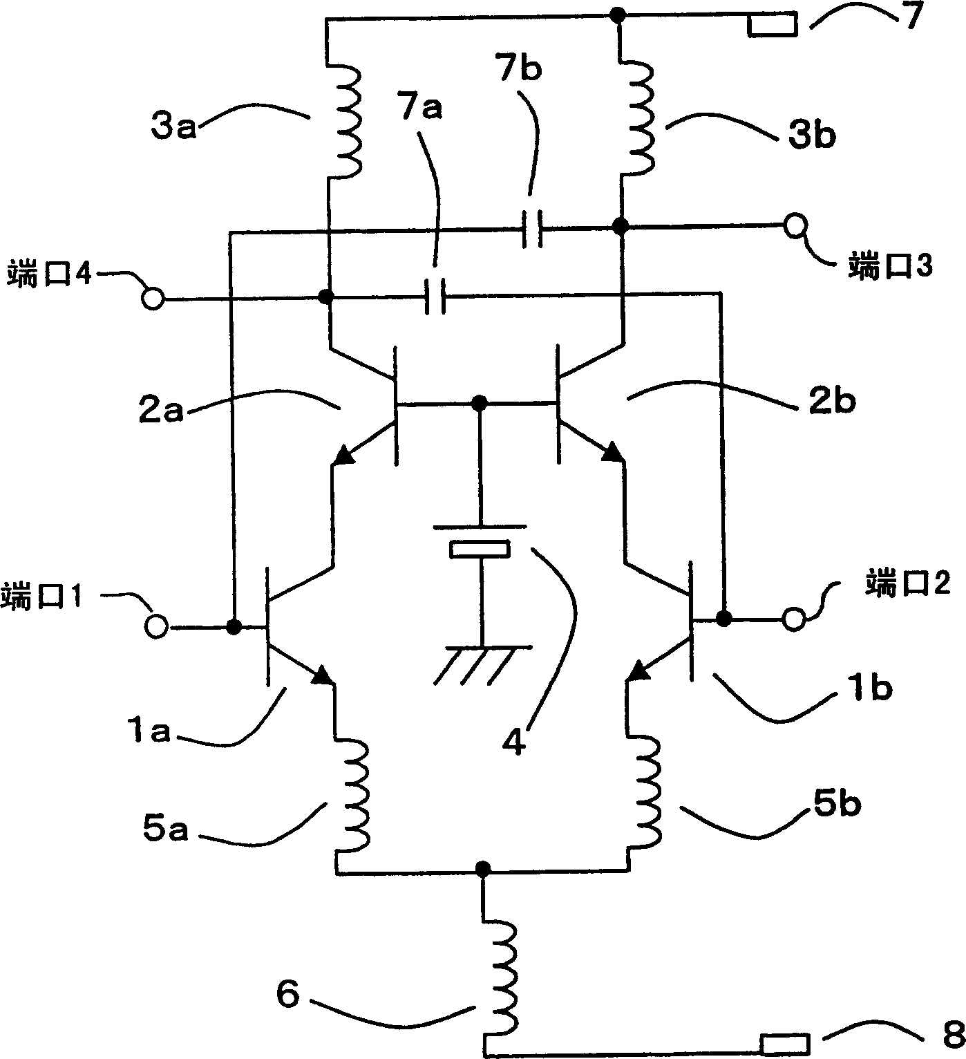
[0086] figure 1 is a circuit diagram of a cascode type differential amplifier according to a first embodiment of the present invention. exist figure 1 , the differential amplifier includes transistors 1a and 1b, transistors 2a and 2b, inductors 3a and 3b, bias source 4, inductors 5a and 5b, inductor 6, positive source 7, feedback capacitors 7a and 7b, and ground 8.

[0087] Transistors 1a and 1b form a differential pair for amplification. Mutually inverse signals are input to port 1 connected to the base of the transistor 1a and port 2 connected to the base of the transistor 1b.

[0088] The emitter of transistor 2a is connected to the collector of transistor 1a, thereby forming a cascode amplifier. Similarly, the emitter of transistor 2b is connected to the collector of transistor 1b, thereby forming a cascode amplifier.

[0089] Inductors 5a and 5b are connected in series between the emitters of transistors 1a and 1b. One end of the inductor 6 is connected between the...

no. 2 example

[0110] Figure 6 is a circuit diagram of a cascode differential amplifier according to a second embodiment of the present invention. exist Figure 6 In , elements similar to those of the differential amplifier according to the first embodiment are denoted by the same symbols, and their detailed descriptions are omitted. From Figure 6 It can be clearly seen that the differential amplifier according to the second embodiment includes passive element circuits 407a and 407b each composed of passive elements such as capacitors, resistors, inductors, etc., and does not include the differential amplifier according to the first embodiment. The feedback capacitor included in the amplifier.

[0111] Figure 7 is a specific example diagram showing the circuit configuration of the passive element circuits 407a and 407b. The circuit structures of the passive element circuits 407a and 407b are the same, so the following description is only for the circuit structure of the passive eleme...

no. 3 example

[0122] In RF amplifiers or local amplifiers, it is necessary to enhance reverse insulation characteristics within a limited predetermined frequency band. Therefore, it is necessary to provide a circuit to control the band-pass amplitude and phase characteristics of the passive element circuit within a limited frequency band, and also to prevent abnormal oscillation due to positive feedback in frequency bands other than the limited frequency band.

[0123] Figure 10 is a circuit diagram of a cascode differential amplifier according to a third embodiment of the present invention. exist Figure 10 In , elements similar to those of the differential amplifier according to the first embodiment are denoted by the same symbols, and thus their descriptions are omitted. From Figure 10 As can be seen, in the third embodiment, passive element circuits 807a and 807b composed of capacitors and resistors and a parallel resonance circuit composed of capacitors and inductors are used inst...


PUM


Abstract

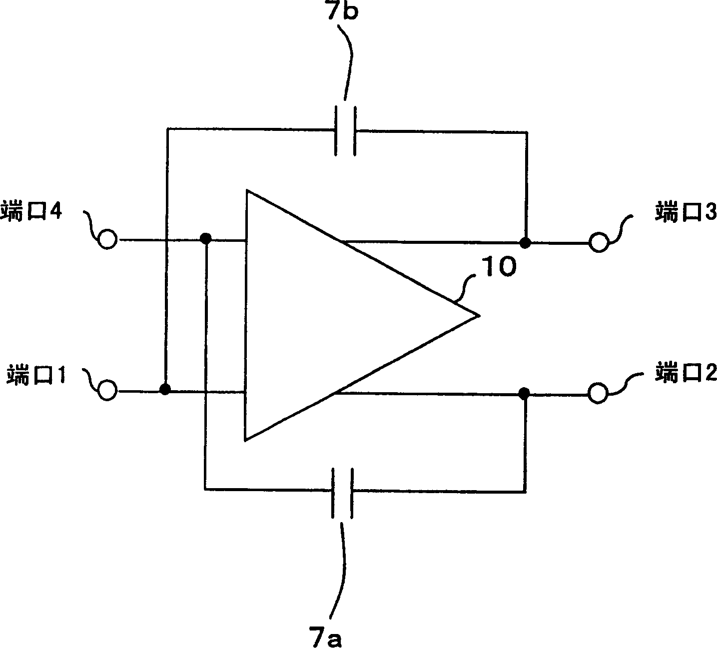
In order to enhance a reverse isolation characteristic of a differential amplifier, which is used as, for example, an RF amplifier or a local amplifier of a mobile telephone, the present invention provides a differential amplifier which includes a differential amplification circuit (10) for amplifying a difference in potential between two input signals in reverse phase with each other, which are inputted into Port1 and Port2, and for outputting two output signals in reverse phase with each other from Port3 and Port4; a feedback capacitor (7a) connected between Port1 and Port4; and a feedback capacitor (7b) connected between Port2 and Port3. Signals for canceling feedback signals are inputted into input terminals via the feedback capacitors (7a and 7b), respectively, whereby it is possible to enhance the reverse isolation characteristic of the differential amplifier.

Description

(1) Technical field [0001] The present invention relates to high-frequency circuits, amplifiers, mixers and radio circuits using them, and more particularly to high-frequency differential circuits, differential amplifiers, differential mixers, differential oscillators and radio circuits using them. (2) Background technology [0002] In differential amplifiers used in high-frequency circuits, it is necessary to enhance their reverse insulation characteristics so as not to lower the power amplification factor. The so-called enhanced reverse isolation as used here refers to the suppression of the so-called negative feedback effect from the output feedback to the input that lowers the input signal level. Conventionally, the configuration of a differential amplifier using a cascode is considered to be effective in enhancing reverse isolation characteristics (see "A fully integrated PLL frequency synthesizer LSI for mobile communication systems" by Takeshi Yasunaga et al. synthes...

Claims


Application Information

Patent Timeline
Patent Type & Authority Applications(China)
IPC IPC(8): H03F3/45
CPCH03F2203/45546H03F2203/45386H03F2200/294H03F3/45089H03F2200/372H03F3/45094H03F2203/45638H03F2203/45464
Inventor 中谷俊文足立寿史
Owner PANASONIC CORP
Learn More