Mechanical type flies killing device

A fly-killer, a mechanical technology, is applied in the device, application, animal husbandry and other directions of catching or killing insects, which can solve the problems of the effect of fly-killing being affected by the environment, unsanitary and environmentally friendly, and unsightly.

Inactive Publication Date: 2005-02-02
郅勇 +1
View PDF0 Cites 6 Cited by
  • Summary
  • Abstract
  • Description
  • Claims
  • Application Information

AI Technical Summary

Problems solved by technology

Generally, insecticide sprays, high-voltage electric shocks, trapping and other methods are used to kill flies. The effect of killing flies is affected by the environment. These methods of killing flies are not only unsanitary and environmentally friendly, but also unsightly.

Method used


Image

  • Mechanical type flies killing device
  • Mechanical type flies killing device
  • Mechanical type flies killing device

Examples


Embodiment Construction

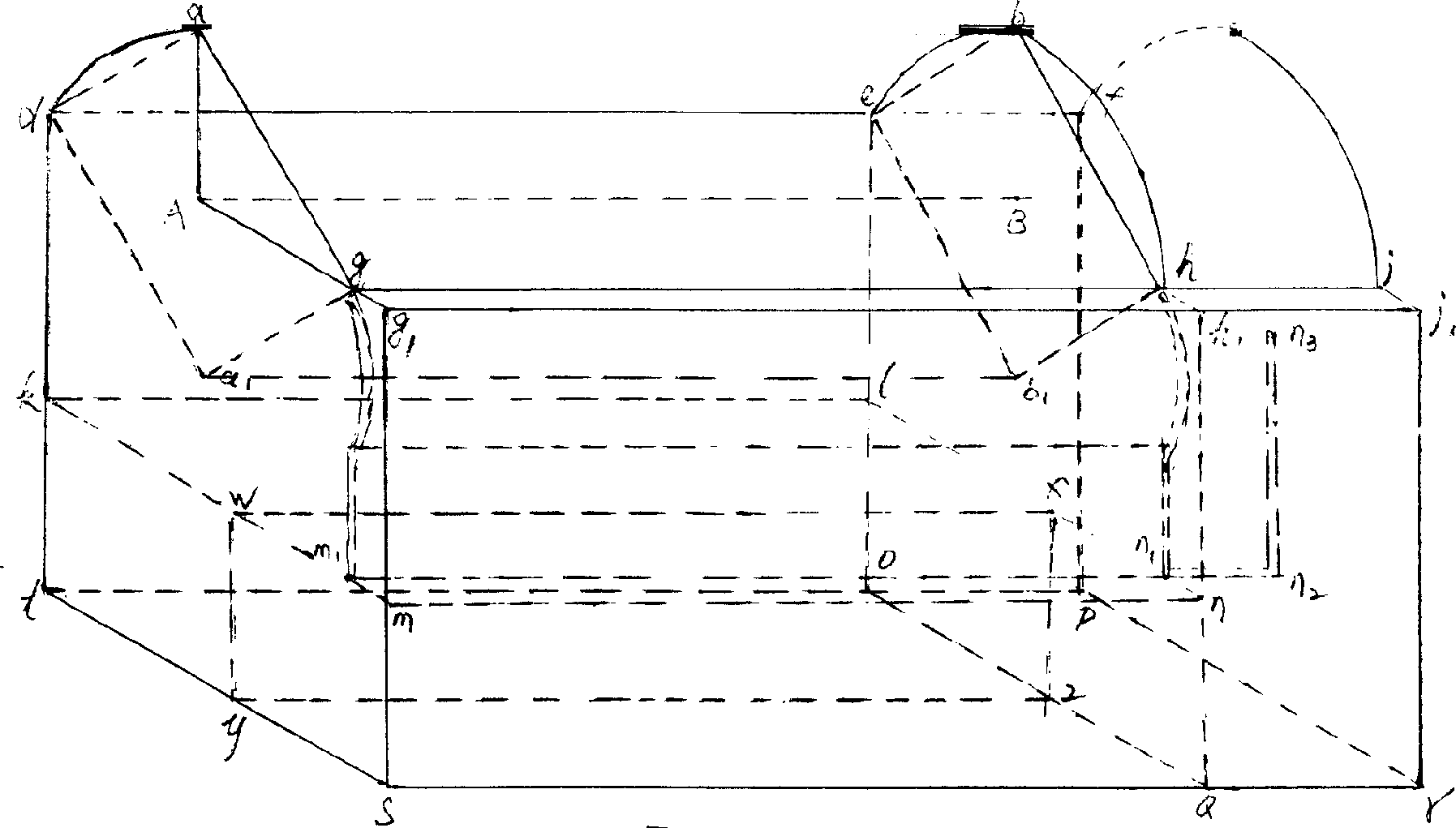
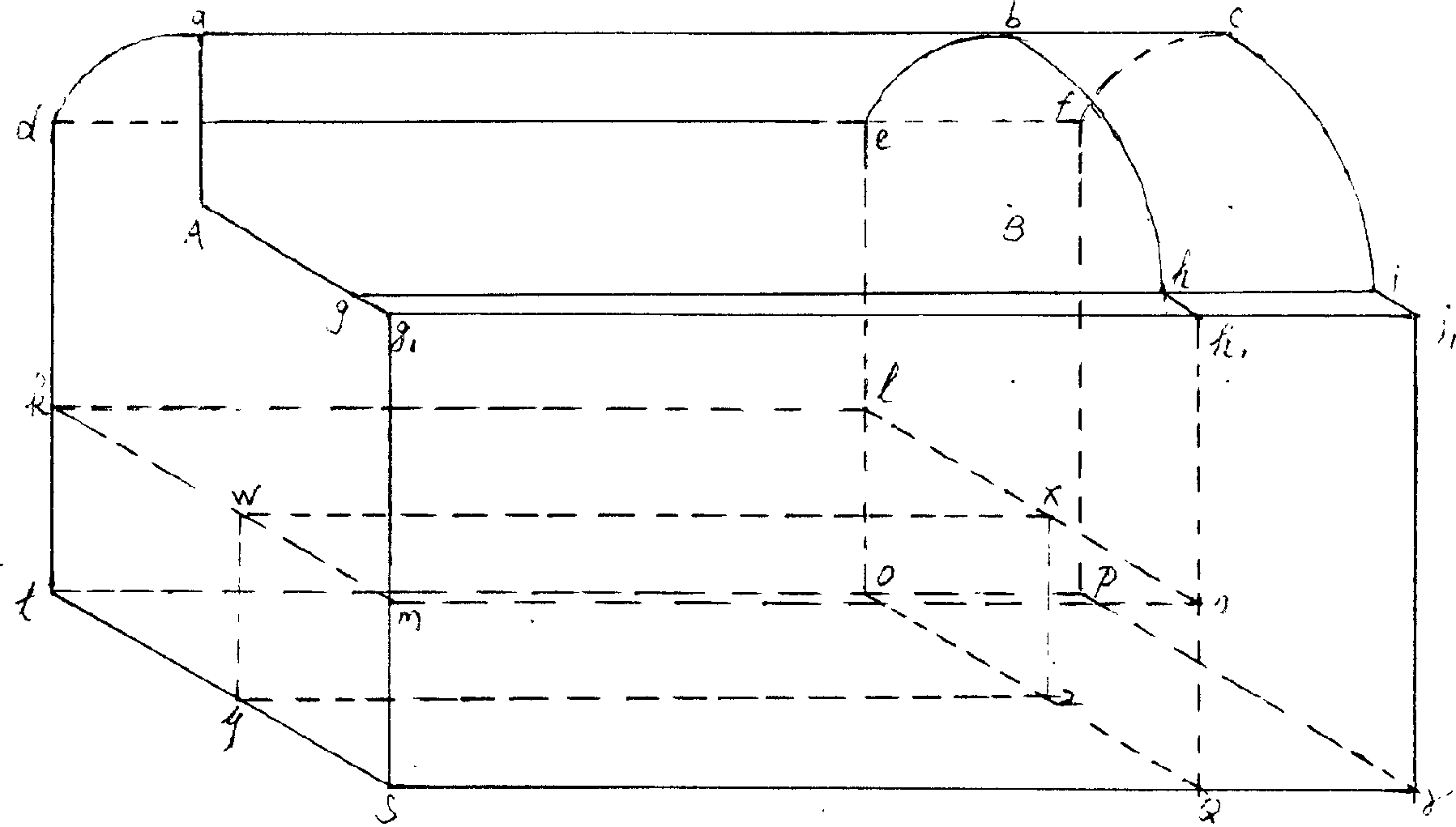
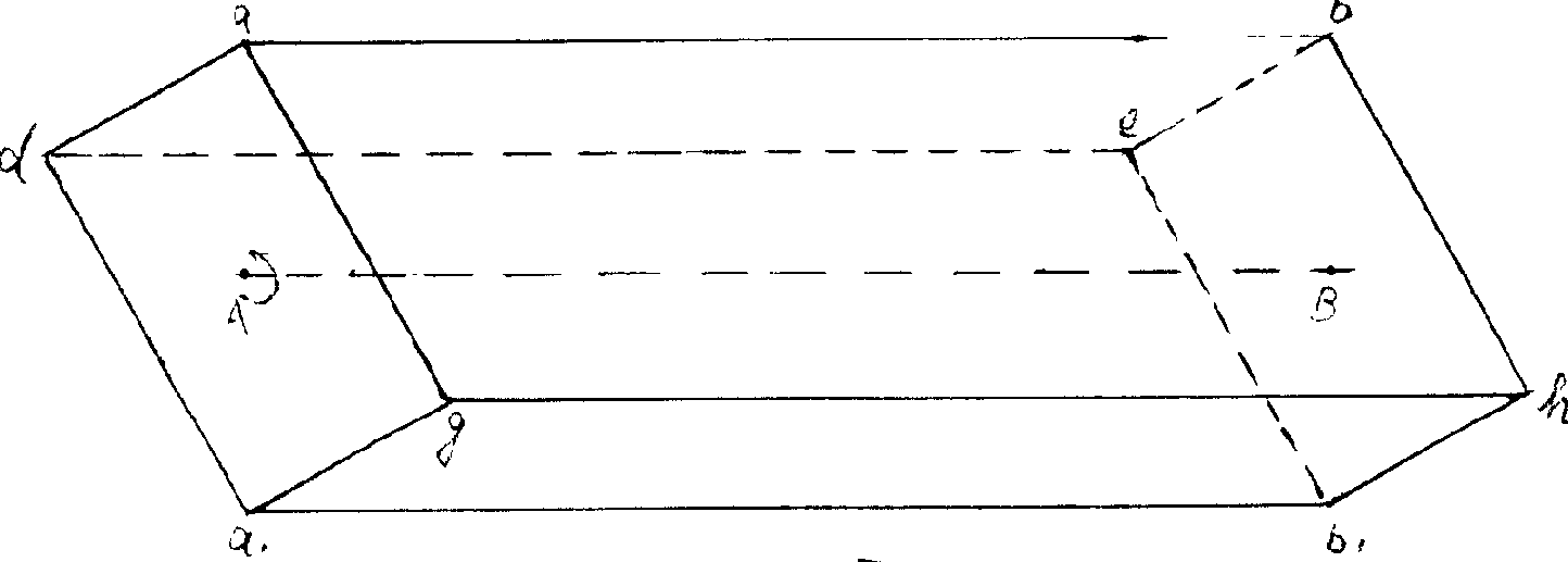
[0017] figure 1 The center point of the second rhombic column coincides with the center point of the arc surface second of the shell, and the four faces abhg, abde, a of the second rhomboid 1 b 1 de, a 1 b 1 hg is coated with fly lure juice, and the four faces of the second rhombic column are exposed on the outer opening of the shell ( figure 1 Aabhg), at the exposed mouth of the shell ( figure 1 The surface of the second prism at Aabhg) is coated with fly-attracting juice to attract flies to attach to its surface. The motor drives the second prism through the gear set to rotate counterclockwise at the angular speed of the second hand of the clock. The second prism surface attached to the fly passes through the transparent shell. arc surface ( figure 1 abde), arc surface ( figure 1 The space established between abde) and the second rhombic column makes the distance between the water chestnut attached to the second rhomboid and the second rhombic column 1mm, so as to achi...


PUM


Abstract

Disclosed is a mechanical flies eradicating apparatus with the functions of sanitary cleaning, environmental protection and contamination prevention, it comprises a casing, a second column, a shutter, a connecting rod and piston, a gear cluster, an electromechanical power supply or spiral power spring, and a gathering box.

Description

technical field; [0001] The invention relates to a mechanical fly killing device powered by mechanical energy or electric energy. Background technique; [0002] Some working environments require sanitation and environmental protection, such as sericulture, catering, and food processing. Generally, insecticidal sprays, high-voltage electric shocks, trapping and other methods are used to kill flies. The effect of killing flies is affected by the environment. These methods of killing flies are not only unhygienic and environmentally friendly, but also unsightly. The device takes into account sanitation and cleanliness, environmental protection and pollution-free, and the fly killing effect is not affected by the fly killing environment (such as: open-air dining spots). content of the invention; [0003] The device overcomes the negative effects of fly killing, keeps the fly killing place hygienic, clean, environmentally friendly and pollution-free (including no visual pollut...

Claims


Application Information

Patent Timeline
Patent Type & Authority Applications(China)
IPC IPC(8): A01M1/10
Inventor 郅勇
Owner 郅勇
Why Eureka
Try Eureka