
Liquid crystal display panel

A technology of liquid crystal display panel and display unit, which is applied to static indicators, instruments, etc., can solve problems such as affecting the general operation of the driver 11, metal perforation in the wire bonding area, and inability to withstand high energy.

Inactive Publication Date: 2005-01-05
AU OPTRONICS CORP
View PDF0 Cites 4 Cited by
  • Summary
  • Abstract
  • Description
  • Claims
  • Application Information

AI Technical Summary

Problems solved by technology

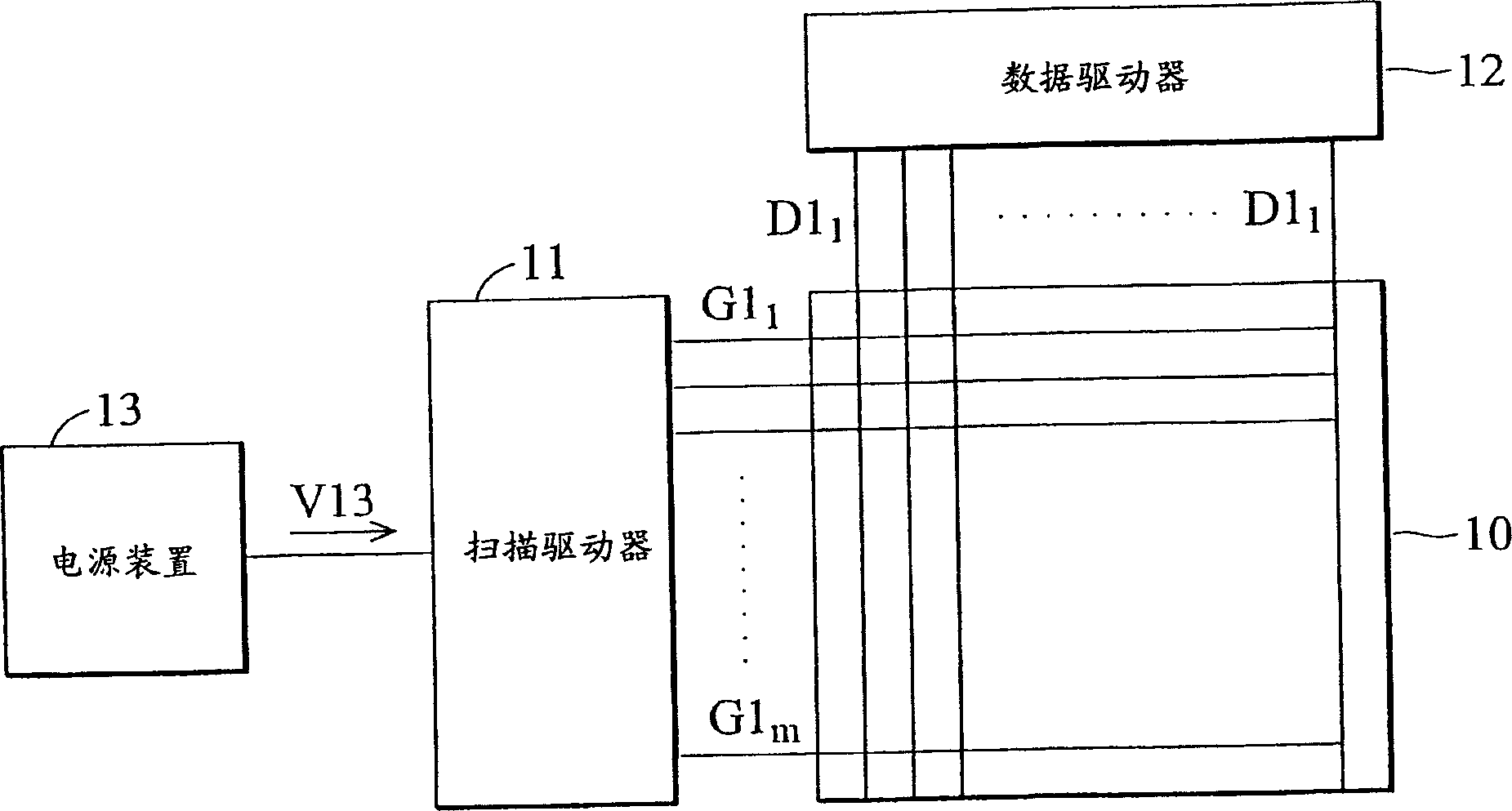
[0005] However, since the scan driver 11 simultaneously outputs all scan signals to the scan electrodes G1 when the shutdown and startup procedures are executed. 1 to G1 m , causing the output energy of the power supply device 13 to be concentrated, and the scan driver 11 cannot sequentially output scan signals to the scan electrodes G1 as in normal operation. 1 to G1 m , and disperse the energy
Therefore, when the scan driver 11 simultaneously outputs all the scan signals to the scan electrode G1 1 to G1 m When the scanning signal is transmitted, the bonding area (Vgh bonding area) cannot bear the high energy from the power supply device 13
After several times of closing and opening procedures, the metal in the wiring area is perforated, which affects the general operation of the driver 11

Method used


Image

  • Liquid crystal display panel
  • Liquid crystal display panel
  • Liquid crystal display panel

Examples


Embodiment

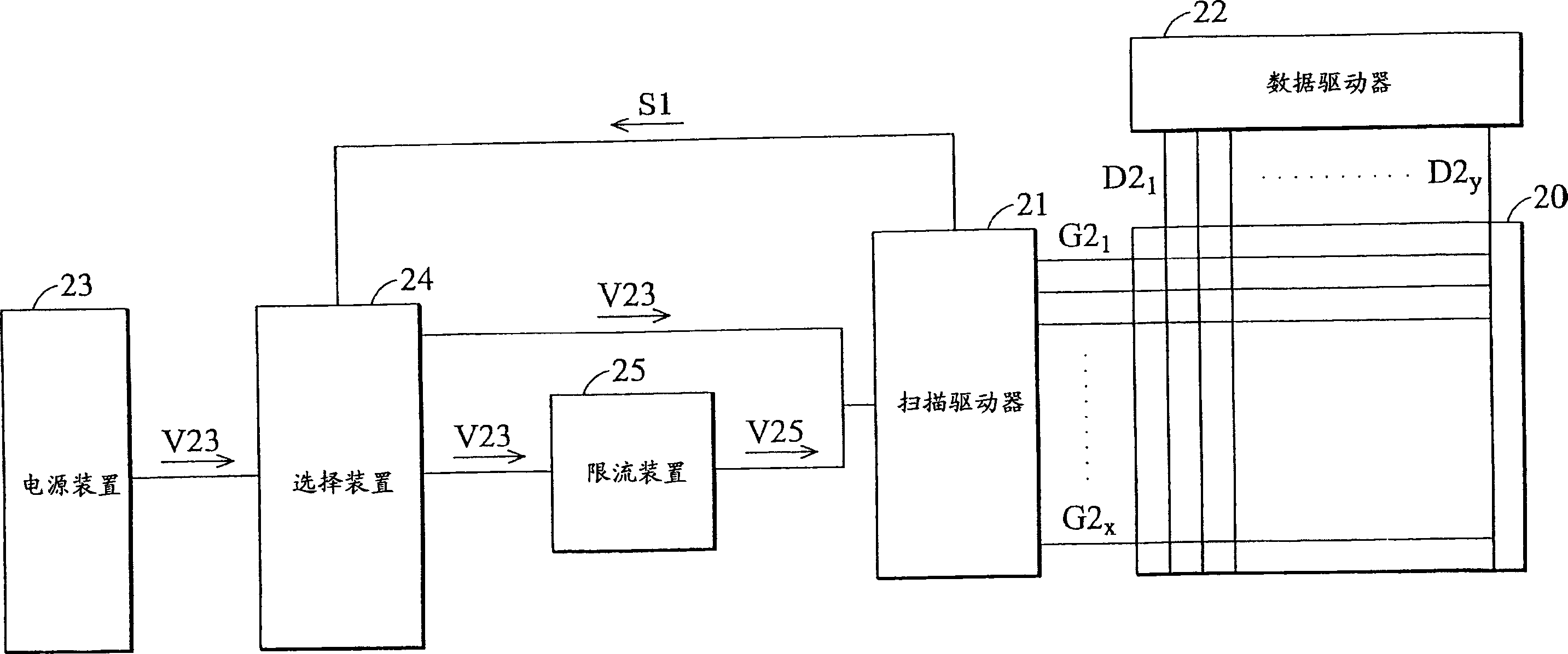
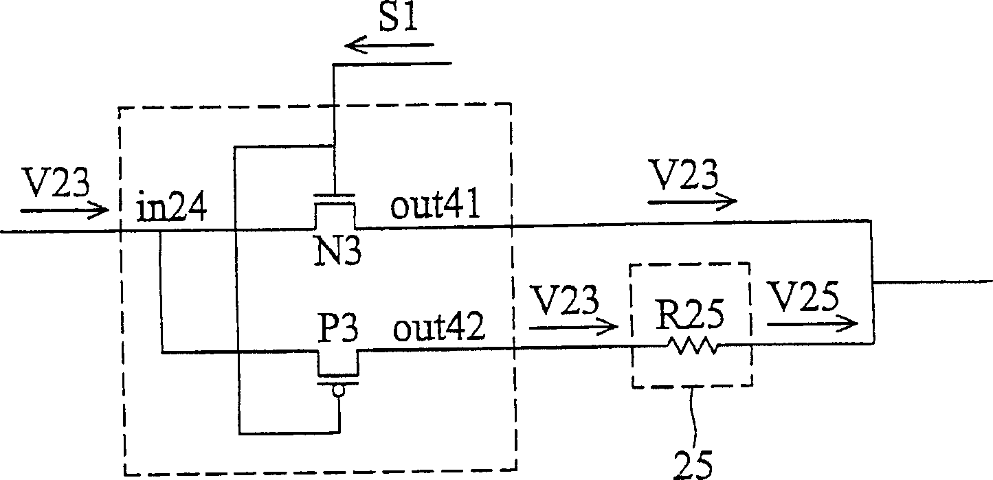
[0038] figure 2 It is a block diagram showing the structure of the liquid crystal display panel of the present invention. The liquid crystal display panel includes a display unit array 20 , a scan driver 21 , a data driver 22 , a power supply device 23 , a selection device 24 and a current limiting device 25 . The display unit array 20 is composed of a plurality of interlaced scanning electrodes G2 l to G2 x and data electrode D2 l to D2 n Composed, and each alternate scan electrode and data electrode corresponds to a display unit. The power supply unit 23 provides a voltage signal V23 4 to the selection device 24 . When the liquid crystal display panel operates normally, the selection device 24 couples its input terminal in24 to the output terminal out41 , so that the power supply device 23 directly provides the voltage signal V23 to the scan driver 21 . Next, the scan driver 21 sequentially outputs the voltage signal V23 to the scan electrode G2 1 to G2 x , so as t...


PUM


Abstract

A liquid crystal display. The liquid crystal display having a power device, a display unit array, a scan driver, a selection device, and a current limiting device. In normal operation of the liquid crystal display, according to the operation of the selection device, a voltage signal applied from the power device is directly applied to the scan driver according to the selection device, and the scan driver sequentially outputs scan signals to scan electrodes. During shutdown and power on processes of the liquid crystal display, according to the operation of the selection device, the voltage signal applied from the power device is applied to the scan driver through the current limiting device, limiting the instantaneous current from the power device. Moreover, the scan driver simultaneously outputs all the scan signals to erase charges within all the display units.

Description

technical field [0001] The present invention relates to a flat display, in particular to a liquid crystal display panel, which is suitable for reducing the instantaneous current borne by the scanning driver when the liquid crystal display panel is closed and opened. Background technique [0002] figure 1 is a structural diagram showing a conventional liquid crystal display panel system. A conventional liquid crystal display panel includes a display unit array 10 , a scan driver 11 , a data driver 12 and a power supply device 13 . The display unit array 10 is composed of a plurality of interlaced scan electrodes and data electrodes D1 1 to D1 n Composed of, and each staggered scan electrode G1 1 to G1 m and the data electrode correspond to a display unit. The power supply device 13 provides a voltage signal V13 to the scan driver 11 . When the liquid crystal display panel is in normal operation, the scan driver 11 sequentially outputs the voltage signal V13 to the scan...

Claims


Application Information

Patent Timeline
IPC IPC(8): G02F1/133G09G3/36
CPCG09G3/3648G09G2330/025G09G2330/02G09G2310/0245
Inventor 黄世雄
Owner AU OPTRONICS CORP
Learn More