


Quick Research
Generate reliable direction feasibility study reports for your R&D in just a few steps.

Technical Q&A
Discover and master advanced knowledge NOW. Basics, ideas, possibilities, all at once.

Find Solutions
As an expert in R&D theories, this can generate solutions to your technical problems instantly.

Evaluate Feasibility
Analyze your overall solution with one click, know your potential R&D risks in advance.

Monitor Landscape
Get weekly tech updates, stay abreast of the latest tech innovations and key insights.
Heating cooker
A technology for a cooking device and a cooking cavity, which is applied to heating methods, electric heating fuels, steam cooking utensils, etc., can solve problems such as heating and cooking devices that are not suitable for steaming.
- Summary
- Abstract
- Description
- Claims
- Application Information
AI Technical Summary
Problems solved by technology
Method used
Image


Examples
Embodiment Construction
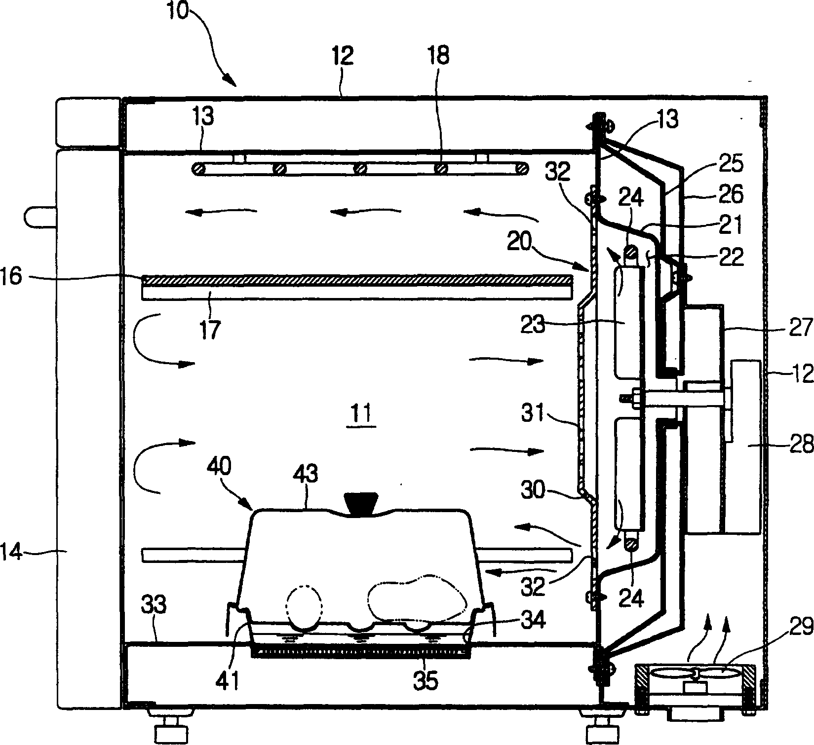
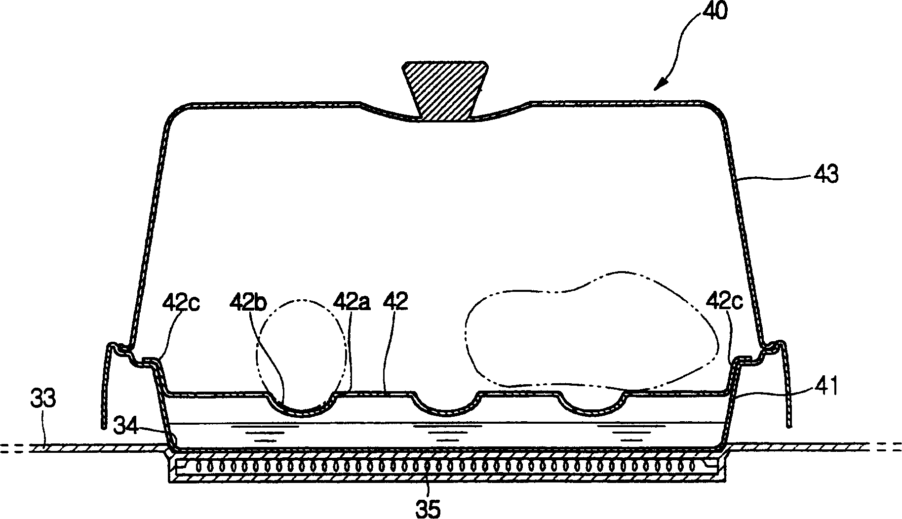
[0017] Specific embodiments of the present invention will now be described in detail with reference to the examples shown in the drawings, wherein like reference numerals refer to like parts throughout.
[0018] figure 1 and 2 is a schematic diagram of the heating and cooking device according to the present invention. As shown in the figure, the heating and cooking device according to the present invention is constituted by a cabinet 10 defining a cooking cavity 11 therein. The cabinet body 10 has two shells, namely an outer shell 12 and an inner shell 13 . The shell 12 is made of thin steel plate and defines the exterior of the cabinet 10 . The inner shell 13 defines the cooking cavity 11 therein and is disposed within the outer shell 12 with a maintenance clearance therebetween. The cooking cavity 11 defined in the inner case 13 is open at its front so that a user puts food into the cooking cavity 1 or takes food out of the cooking cavity 11 . The front opening of the c...
PUM
 Abstract
Description
Claims
Application Information
 - R&D Engineer
- R&D Manager
- IP Professional
- Industry Leading Data Capabilities
- Powerful AI technology
- Patent DNA Extraction
Browse by: Latest US Patents, China's latest patents, Technical Efficacy Thesaurus, Application Domain, Technology Topic, Popular Technical Reports.
© 2024 PatSnap. All rights reserved.Legal|Privacy policy|Modern Slavery Act Transparency Statement|Sitemap|About US| Contact US: help@patsnap.com