Remote control device for hanging fan

A technology of remote control device and fan, applied in pump control, non-variable-capacity pump, machine/engine, etc., can solve the problems of wasting electric energy, inconvenient use, etc., and achieve the effect of convenient use and good stability

Inactive Publication Date: 2004-11-17
KENLI SANHE NEW MATERIAL TECH
View PDF0 Cites 0 Cited by
  • Summary
  • Abstract
  • Description
  • Claims
  • Application Information

AI Technical Summary

Problems solved by technology

[0002] People often use ceiling fans to keep cool in summer, and its control is mechanical, which has defects such as inconvenient use and waste of electric energy.

Method used


Image

  • Remote control device for hanging fan
  • Remote control device for hanging fan

Examples


Embodiment approach

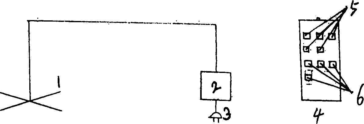
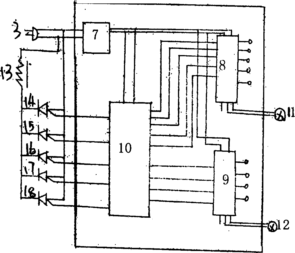
[0009] Depend on figure 1 , figure 2 It can be seen that the fan main body 1 is connected to the remote control receiver 2 and the power plug 3 , and the remote control 4 is equipped with a gear button 5 and a time control button 6 . A rectifier 7, a gear sensor 8, a time reactor and a controller 10 are installed in the remote control receiver, and a gear indicator 11, a time indicator 12, a fan coil connector 13 and five gears are formed on the outside of the remote controller. Rotating speed control silicon controlled rectifier 14,15,16,17,18 forms. And be connected with power plug 3, ceiling fan coil connector 13 to form ceiling fan control operation circuit. The whole action process is powered by the rectifier 7, and the gear position sensor 8 turns on the gear position controller according to the speed signal of the remote controller 4, turns on the corresponding control circuit 10, and controls the thyristor to make the electric fan rotate. When it is turned on, the s...


PUM


Abstract

The invention is a kind of remote control device of ceiling fan which belongs to household appliance, it is convenient and it can save energy. The device is mainly made up of the ceiling fan and the remote receiver, and power plug, and it is controlled by the controller, in the controller there sets a gear button and time control button, the main structure of the remote controller is made up of commutator, gear inducer and time inducer and controller. It is convenient, energy-saving, and the stabilization is good.

Description

1. Technical field: [0001] The invention belongs to electrical products of people's daily life, and is mainly used for a remote control device of a fan. 2. Background technology: [0002] People usually use ceiling fan to take cool in summer, and its control is mechanical control, which has defects such as inconvenient use and waste of electric energy. 3. Contents of the invention: [0003] The purpose of the present invention is to provide a remote control device for a ceiling fan, which solves the problems of convenient use and energy saving. The device is mainly composed of a ceiling fan, a remote control receiver, a remote control, and a power plug. The remote control is equipped with a gear button and a time control button. The remote control receiver is equipped with a rectifier, a gear sensor, a time sensor, and a controller. constitute. [0004] The main beneficial effects of the invention are convenient use, energy saving and good stability. 4. Description of ...

Claims


Application Information

Patent Timeline
IPC IPC(8): F04D27/00
Inventor 梁延民
Owner KENLI SANHE NEW MATERIAL TECH
Why Eureka
Try Eureka