
Vote logic block including running and maintenance overlay in remote control system

A technology of voting logic and control system, which is applied in general control system, control/regulation system, program control in sequence/logic controller, etc. It can solve problems such as equipment and material damage, cumbersome programming steps, and factory personnel injury

Active Publication Date: 2004-10-13
FISHER-ROSEMOUNT SYST INC
View PDF2 Cites 6 Cited by
  • Summary
  • Abstract
  • Description
  • Claims
  • Application Information

AI Technical Summary

Problems solved by technology

[0005] While in the past, configuration or safety engineers sometimes manually programmed voting logic into safety system controllers using different programming languages, unfortunately this programming step was tedious, time-consuming and error-prone, which could be serious , because a failure of the safety system to function properly can result in serious injury or death to plant personnel, as well as damage to potentially tens of thousands of dollars worth of equipment and materials in the plant

Method used


Image

  • Vote logic block including running and maintenance overlay in remote control system
  • Vote logic block including running and maintenance overlay in remote control system
  • Vote logic block including running and maintenance overlay in remote control system

Examples


Embodiment Construction

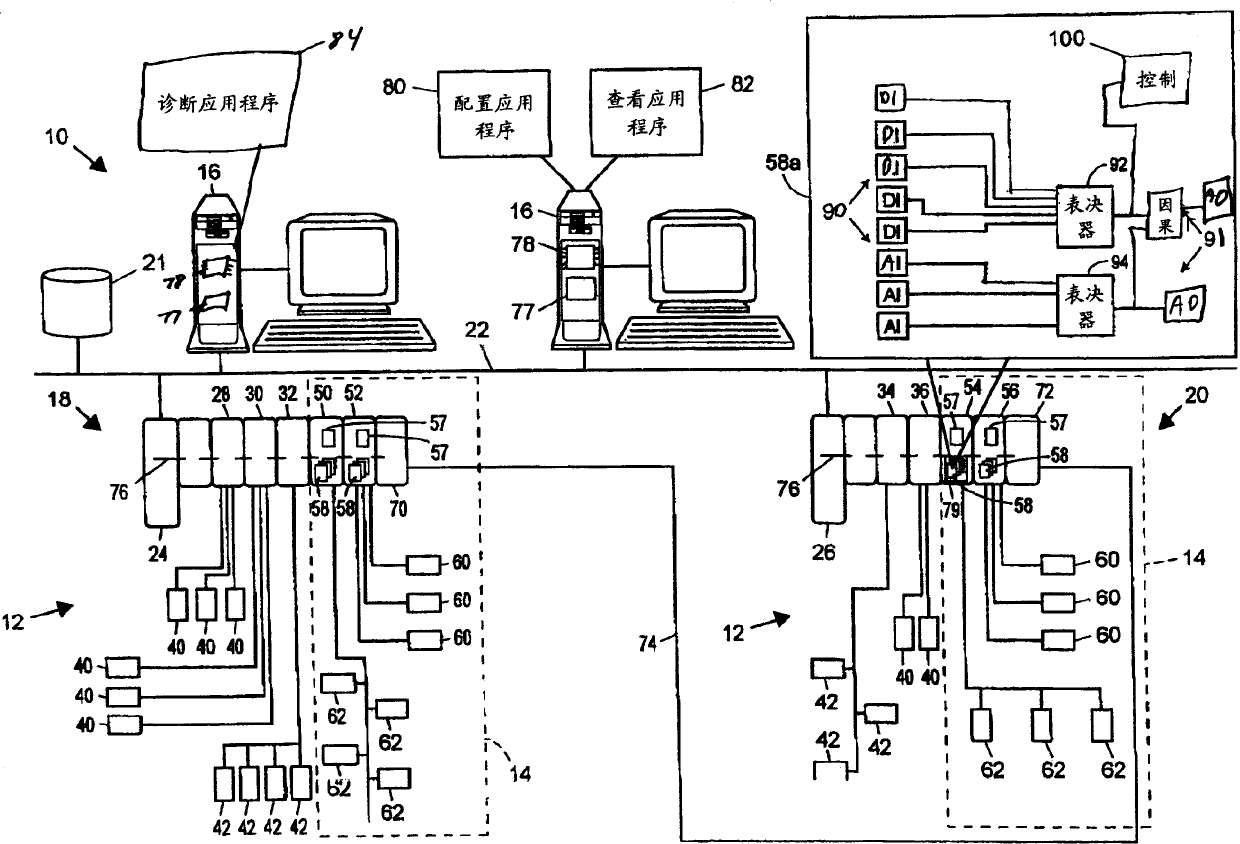
[0013] Referring now to FIG. 1 , a process plant 10 includes a process control system 12 integrated with a safety system 14 (represented by dashed lines), which generally operates as a safety-equipped system (SIS) to monitor and override information provided by the process control system 12. control to maximize the possible safe operation of the process device 10. The process device 10 also includes one or more host workstations, computers or user interfaces 16 (which may be any type of personal computer, workstation, PDA, etc.), which can be accessed by plant personnel such as process control administrators, maintenance personnel, security engineers, etc.) to visit. In the example shown in FIG. 1 , two user interfaces 16 are shown connected to two separate process control / safety control nodes 18 and 20 and to a configuration database 21 via a common communication line or bus 22 . Communication network 22 may be implemented using any desired bus-based or non-bus-based hardwar...


PUM


Abstract

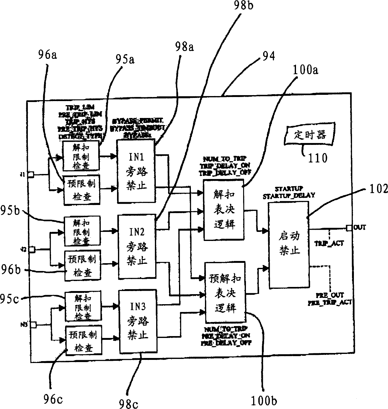
A voter function block, which can be integrated into a function block diagram programming environment in a process plant control or safety system, implements voter logic in conjunction with providing operational and maintenance overrides which may be set to override individual inputs to the voter function block as well as to override the output of the voter function block. The voter function block, which is easy to create, use, test, debug and document, includes one or input limit detection units which detect if a particular redundant input has reached a specified limit indicating a condition within the process plant, an override unit that may be set by a user to override the consideration of that input in the voting function, a voting logic entity that determines if a trip condition exists based on the values of the valid or non-inhibited inputs, and an inhibit block that may used to override the output of the voter logic block during, for example, a startup or other operational condition. The voter function block may be integrated into a process control or safety system by being communicatively connected to other function blocks, such as to analog or digital input function blocks, analog or digital output function blocks, control function blocks, cause and effect function blocks which implement cause and effect logic, etc. within the process control or safety programming environment.

Description

technical field [0001] The present invention relates generally to process control and safety systems for use in process plants, and more particularly to systems including voting logic with operation and maintenance override functionality. Background technique [0002] Process control systems, like those used in chemical, petroleum, or other processes, typically include one or more process controllers communicatively coupled to at least one host computer or The digital combination is bus or line communicatively coupled to one or more field devices. These field devices can be, for example, valves, valve positioners, switches and transmitters (eg, temperature, pressure, and flow rate sensors) that perform functions within the process device, such as opening or closing valves, and measuring process variables. Process controllers receive signals from field devices representing process measurements and / or other information about the field devices, use this information to implemen...

Claims


Application Information

Patent Timeline
Patent Type & Authority Applications(China)
IPC IPC(8): G05B9/02G05B9/03G05B23/02
CPCG05B9/03G05B9/02G05B23/02
Inventor 迈克尔·G·奥特加里·劳丹尼斯·史蒂文森罗伯特·哈夫科斯特戈弗雷·谢里夫
Owner FISHER-ROSEMOUNT SYST INC
Learn More