
Colour filter substrate, and displaying device

A technology for color filter substrates and display devices, which is applied in the direction of instruments, optical filters, measuring device casings, etc.

Inactive Publication Date: 2004-08-11
SHARP KK
View PDF2 Cites 2 Cited by
  • Summary
  • Abstract
  • Description
  • Claims
  • Application Information

AI Technical Summary

Problems solved by technology

In fact, despite this, these problems can arise not only in the above-mentioned display devices, but also in any type of display device in which the misalignment of the color filter substrate with other substrates affects the pixel aperture ratio.

Method used


Image

  • Colour filter substrate, and displaying device
  • Colour filter substrate, and displaying device
  • Colour filter substrate, and displaying device

Examples


Embodiment Construction

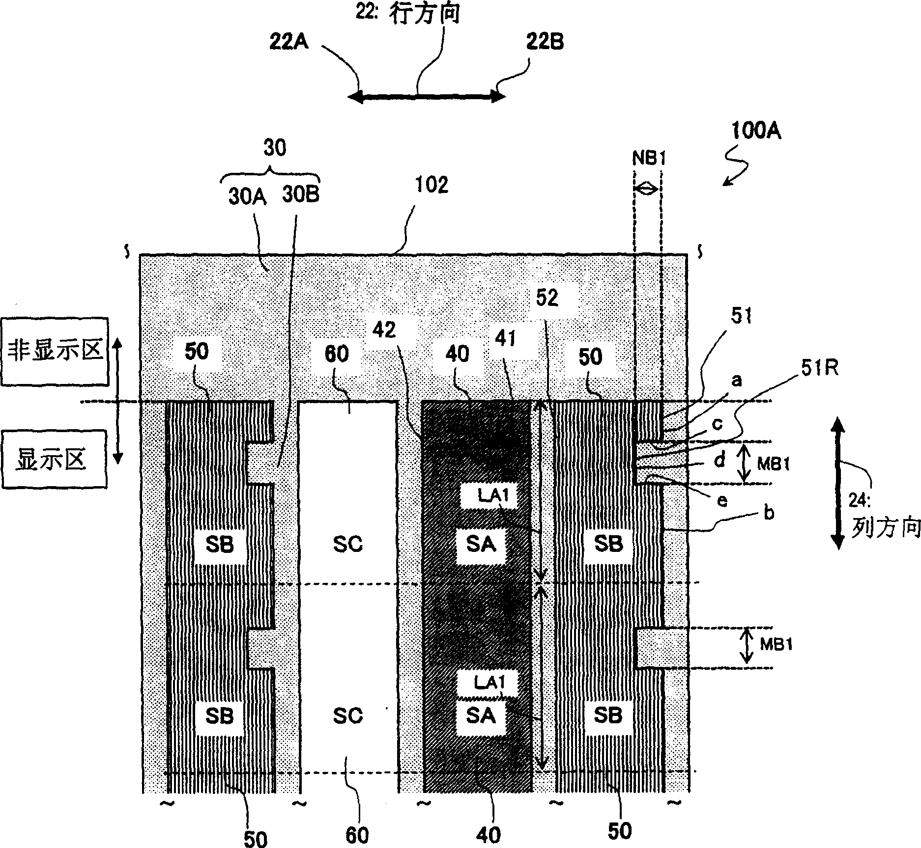
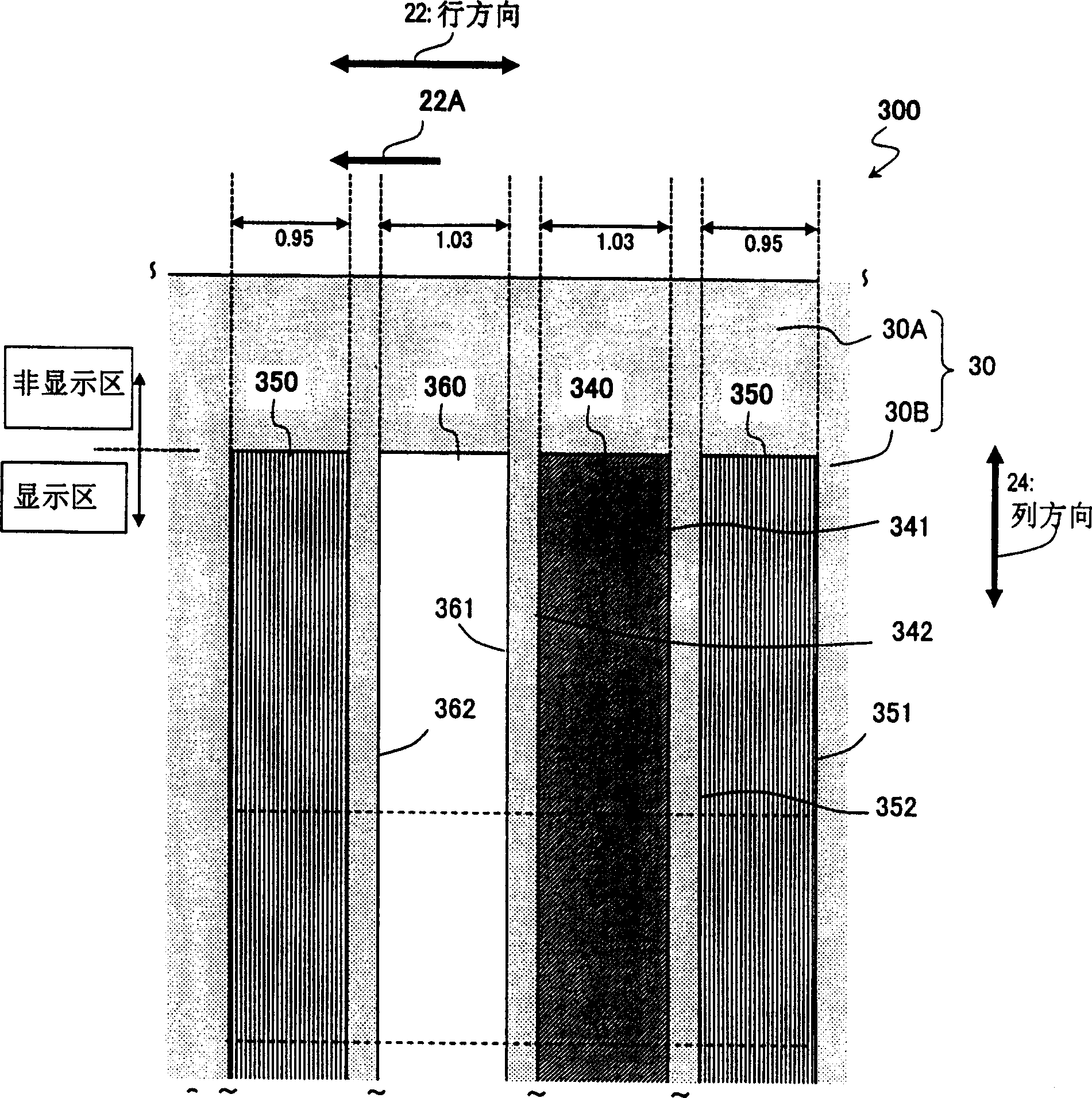
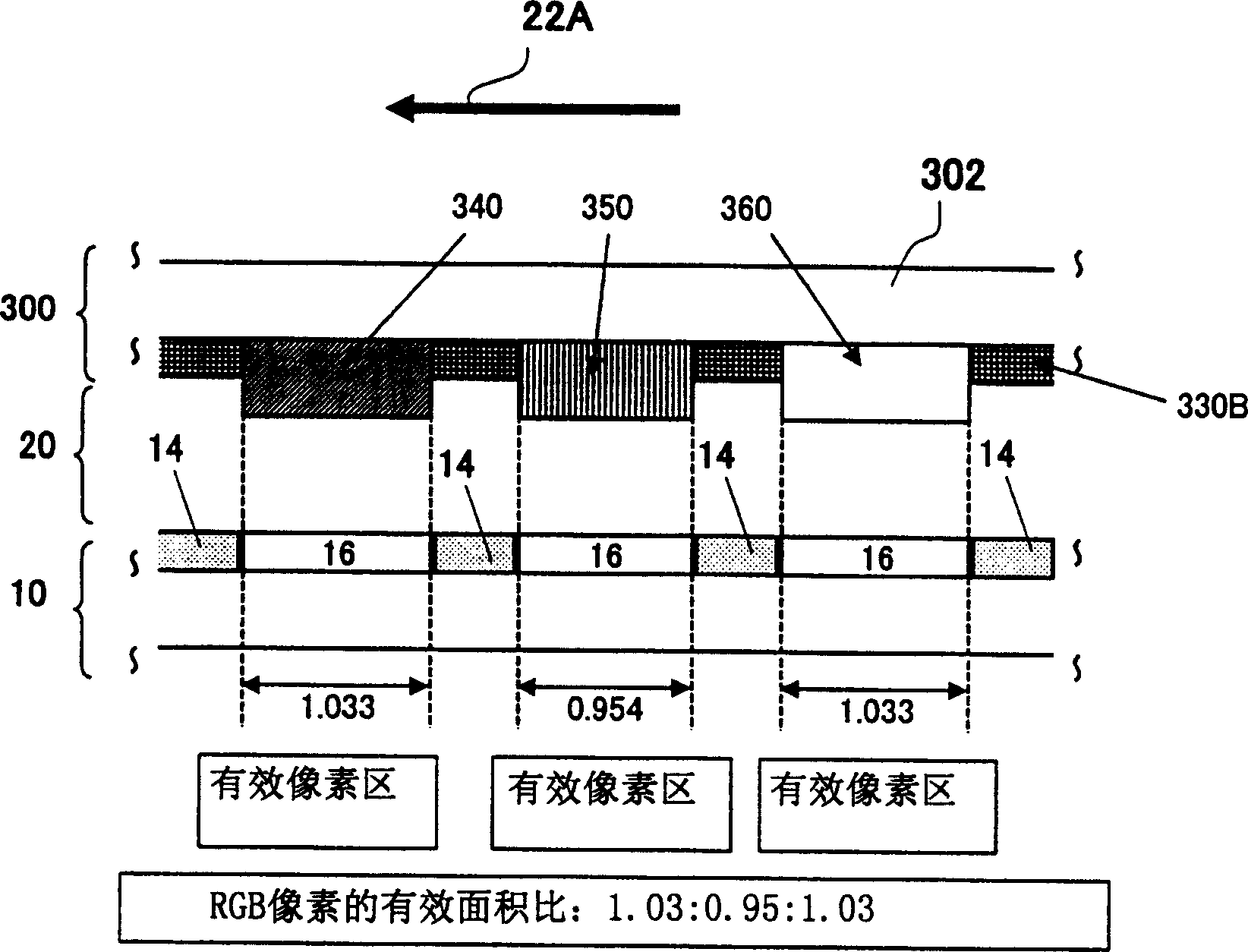
[0066] Hereinafter, color filter substrates according to various preferred embodiments of the present invention will be described with reference to the accompanying drawings. The color filter substrate according to various preferred embodiments of the present invention is preferably used in a display device including pixels arranged in a matrix so as to define columns of pixels in a column direction and rows of pixels in a row direction, respectively. Also, in the color filter substrate according to each preferred embodiment of the present invention, the area of ​​the color filter thereof is adjusted on a color-by-color basis. That is, the area of ​​the color filter in one color is different from the area of ​​the color filter in the other color. In the following preferred embodiments, the present invention will be described as applied to a color filter substrate including color filters arranged in stripes, which is used in an active matrix addressable liquid crystal display d...


PUM


Abstract

A color filter substrate for a display device includes pixels arranged in columns and rows. The substrate includes color filters, each being associated with one of the pixels and including at least two A-color filters in a first color and at least two B-color filters in a second color. Each row is associated with a group of color filters including at least one of the A-color filters and at least one of the B-color filters. Each of the A-color and B-color filters has first and second sides defining a width in the row direction. The area SA of each A-color filter is greater than the area SB of each B-color filter. The first side of each B-color filter has at least one recess, and the first side of each B-color filter has a shape that is defined by forming a recess on the first side of each A-color filter toward the second side thereof in the row direction.

Description

technical field [0001] The present invention relates to a method of manufacturing color filter substrates used in color liquid crystal displays (LCDs) and other display devices. Background technique [0002] An LCD is a relatively small, thin and light-weight display device with relatively low power consumption. Taking advantage of these features, LCDs are currently widely used in various electronic devices. Among them, active matrix addressing LCDs with switching elements are particularly widely used in office automation (OA) devices such as personal computers, visual devices (AV) such as televisions, and mobile phones. Meanwhile, the size, resolution, effective pixel area ratio (ie, aperture ratio), color purity, and other quality parameters of LCDs have been increased or significantly improved in recent years. [0003] The following will refer to Figure 15 Introduce the structure of common active matrix addressable LCD, where Figure 15 A cross-sectional view thereof i...

Claims


Application Information

Patent Timeline
Patent Type & Authority Applications(China)
IPC IPC(8): G02B5/20G02F1/1335
CPCG02F1/133514G02F2201/40G01F15/14G01D11/26
Inventor 德田刚津幡俊英八木敏文
Owner SHARP KK
Learn More