Encoding device

A motion encoder and detector technology, applied in the direction of instruments, conversion sensor output, measuring devices, etc., can solve the problem of increasing size requirements

Inactive Publication Date: 2004-06-30
NOKIA TECH OY
View PDF1 Cites 0 Cited by
  • Summary
  • Abstract
  • Description
  • Claims
  • Application Information

AI Technical Summary

Problems solved by technology

Utilizes a mechanically conductive switch to detect the rotational movement of the key, which increases the size requirements of the device

Method used


Image

  • Encoding device
  • Encoding device
  • Encoding device

Examples


Embodiment Construction

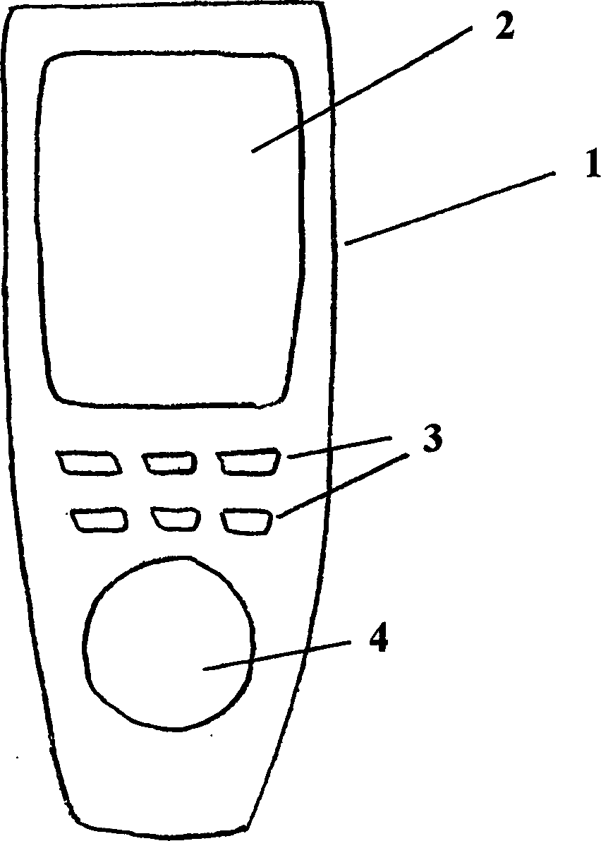
[0019] refer to figure 1 , the radiotelephone 1 shown in the figure includes a radio receiving and transmitting device, an LCD (Liquid Crystal Display) 2 and a plurality of keys 3 completely contained within the housing of the radiotelephone 1 . A plurality of buttons 3 are located below the LCD 2 . The LCD 2 and a plurality of keys 3 are located on the front of the radiotelephone 1 . A rotary dial 4 is also provided, which is located below a plurality of keys 3 . The rotary dial 4 is mounted such that its axis of rotation is perpendicular to the front of the radiotelephone 1 . The rotary dial 4 forms part of an electromagnetic encoder solution for converting motion into an analog output representation. In one embodiment, the electromagnetic encoder is an optical encoder.

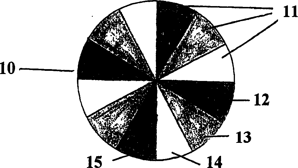
[0020] refer to figure 2 , the disk 10 includes three different reflective surfaces 11 ; of course more reflective surfaces can be used and organized such that each reflective surface constitutes a se...


PUM


Abstract

A motion encoder for use with a rotating key. The motion encoder allows the direction of rotation to be determined by providing elements having different characteristics for the transmission of a IR beam. These elements are arranged in a pattern that allows an IR beam impinging on the elements to trace a path detected as the rotating key turns. The beam being detected after changes in the reflected or transmitted beam indicating the direction of rotation of the beam.

Description

technical field [0001] The invention relates to an electromagnetic motion encoder. Specifically, it involves converting motion information into an analog output representation. Background technique [0002] Radiotelephones typically include a screen and an alphanumeric keypad, wherein a user can enter information into the radiotelephone using the alphanumeric keypad while displaying that information on the screen. The size of a wireless telephone is primarily limited by the screen and alphanumeric keypad. It is desirable for a radiotelephone to be small and compact so that the user can carry the radiotelephone in a pocket. Although both the screen and the keypad can be reduced in size, the screen must be large enough so that the characters displayed on it are large enough for the user to read. The alphanumeric keypad must be large enough to allow the user to enter data without inadvertently pressing two keys at the same time. [0003] It is desirable for a wireless phone...

Claims


Application Information

Patent Timeline
Patent Type & Authority Applications(China)
IPC IPC(8): H04B1/40G01D5/36
CPCG01D5/363G01D5/36H04B1/40
Inventor M·费尔马维G·温格特A·比克
Owner NOKIA TECH OY
Why Eureka
Try Eureka