
Electrical connector

An electrical connector, connector technology, applied in the direction of conductive connection, connection, clamping/spring connection, etc., can solve problems such as cracking

Inactive Publication Date: 2004-05-26
TYCO ELECTRONICS JAPAN GK
View PDF3 Cites 2 Cited by
  • Summary
  • Abstract
  • Description
  • Claims
  • Application Information

AI Technical Summary

Problems solved by technology

Cracks may therefore occur during block forming

Method used


Image

  • Electrical connector
  • Electrical connector
  • Electrical connector

Examples


Embodiment Construction

[0032] Embodiments of the present invention are described below.

[0033] An electrical connector according to an embodiment of the present invention has four male contacts. The tip of each male contact has a mating portion adapted for mating contact. In the mating receptacle of the electrical connector of this embodiment, the mating portions of the male contacts are laterally arranged at predetermined intervals. Also, the present invention is applicable not only to electrical connectors having male contacts but also to electrical connectors having female contacts.

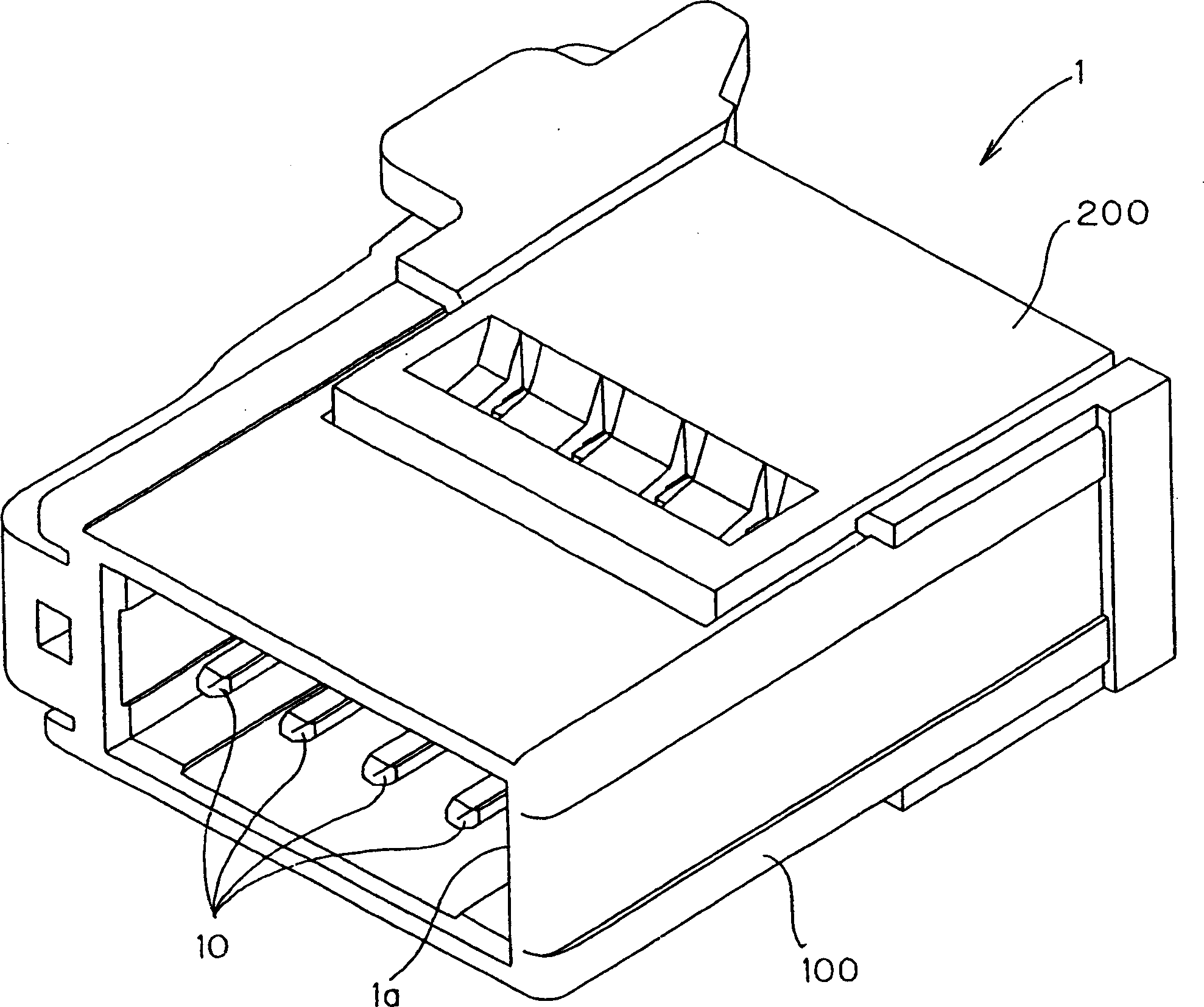
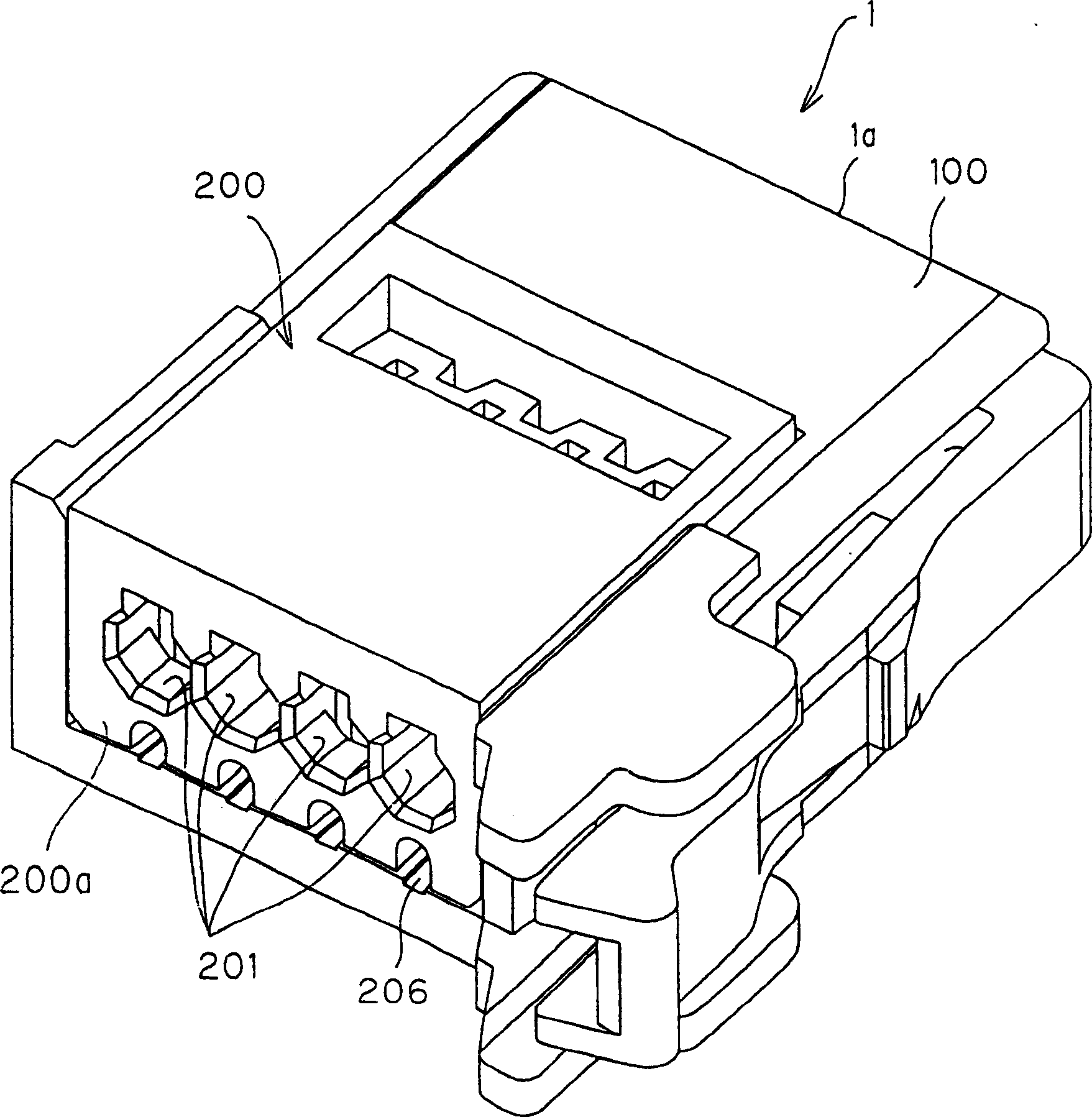
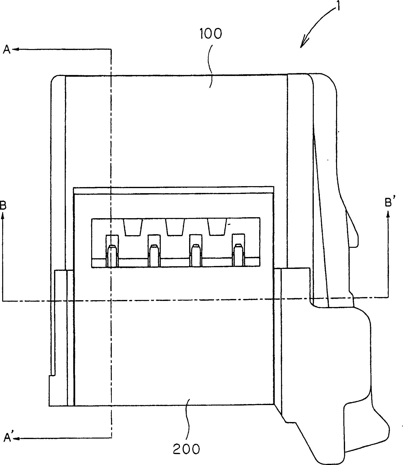
[0034] figure 1 is a perspective view showing the electrical connector of this embodiment obliquely from above the mating connector receiving opening. figure 2 is the perspective view, which starts from figure 1 The electrical connector of this embodiment is shown obliquely above the opposite sides of . image 3 is a plan view showing the electrical connector of this embodiment.

[0035] The electrical co...


PUM


Abstract

Provided is an piercing type electric connector corresponding to a large-diameter wire which regulates a relative movement of the wire and a protruded contact part for long period of time, equipped with a contact having the protruded contact part piercing a coating member of the wire with a core wire coated by the coating member.A block is so arranged that a tip of the protruded contact part juts out inside a hole. A spring member biasing the wire accepted in the hole toward the protruded contact part is fitted at a position opposing the tip of the protruded contact part jutting out inside the hole.

Description

technical field [0001] The present invention relates to a so-called piercing type electrical connector equipped with a contact member having a protruding contact portion piercing a sheath member of an electric wire with which the inner wire of the electric wire is covered. Background technique [0002] Various methods are conventionally known for connecting contacts and wires. These methods include a method using pressure welding to form the connection. Pressure welding is used to connect electric wires having a core wire covered with a sheath member. Contacts formed by this method include a so-called piercing type contact having a sharp protruding contact portion at its end. [0003] For example, Patent Document 1 describes a contact having a protruding contact portion with a sharp end and a pair of press-fit portions flared somewhat outward on both sides of the protruding contact portion and expanded upward. When an electric wire is connected to the contact, the protrud...

Claims


Application Information

Patent Timeline
Patent Type & Authority Applications(China)
IPC IPC(8): H01R13/639H01R4/24H01R4/48
CPCH01R13/506H01R4/2429H01R4/2404H01R4/4809H01R13/639H01R4/24
Inventor 陆一也
Owner TYCO ELECTRONICS JAPAN GK
Learn More