
End support operation cable

A supporting device and cable technology, applied in the direction of shafts and bearings, flexible shafts, linear motion shafts, etc., can solve the problems of increased cost and lower vibration damping performance, and achieve the effect of easy assembly

Inactive Publication Date: 2004-03-31
NIPPON CABLE SYSTEM INC +1
View PDF2 Cites 5 Cited by
  • Summary
  • Abstract
  • Description
  • Claims
  • Application Information

AI Technical Summary

Problems solved by technology

This type of device is light in weight and easy to assemble, but on the other hand, the vibration damping performance is lowered, and it is necessary to install a separate anti-vibration device such as a counterweight according to the situation, which has become a cause of increased cost.

Method used


Image

  • End support operation cable
  • End support operation cable
  • End support operation cable

Examples


Embodiment

[0049] Examples and comparative examples are given below to specifically illustrate the use effect of the terminal support device of the present invention.

[0050] [Example] will Figure 7 The end support 62 is shown mounted to the AT cable. The outer diameter of the damping blocks 15 and 16 is 38 mm, the inner diameter is 16 mm, the thickness of the disc-shaped part 63 is 3.5 mm, the material is EPDM, and the rubber hardness is Hs50. In addition, the degree of clamping of the retaining plate is such that the disk-shaped portion 61 is reduced from its natural thickness to about 1.3 mm. picture Figure 7 This is attached to the support 64 as shown, and the other end of the AT cable is attached to the rod bracket 65 . In this state, a predetermined magnitude of vibration (vibration acceleration Gf) is applied to the end support device 62 at various vibration frequencies in the T direction, B direction, and H direction, and the magnitude of the T-direction vibration transmitt...


PUM


Abstract

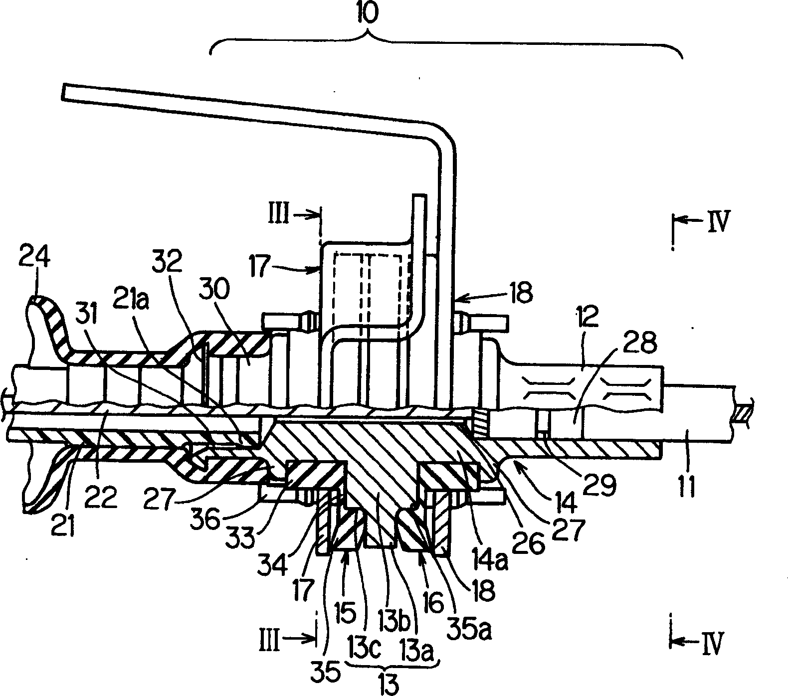
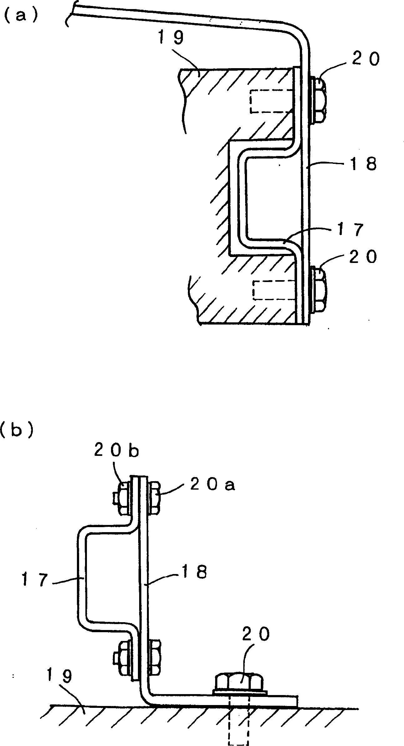
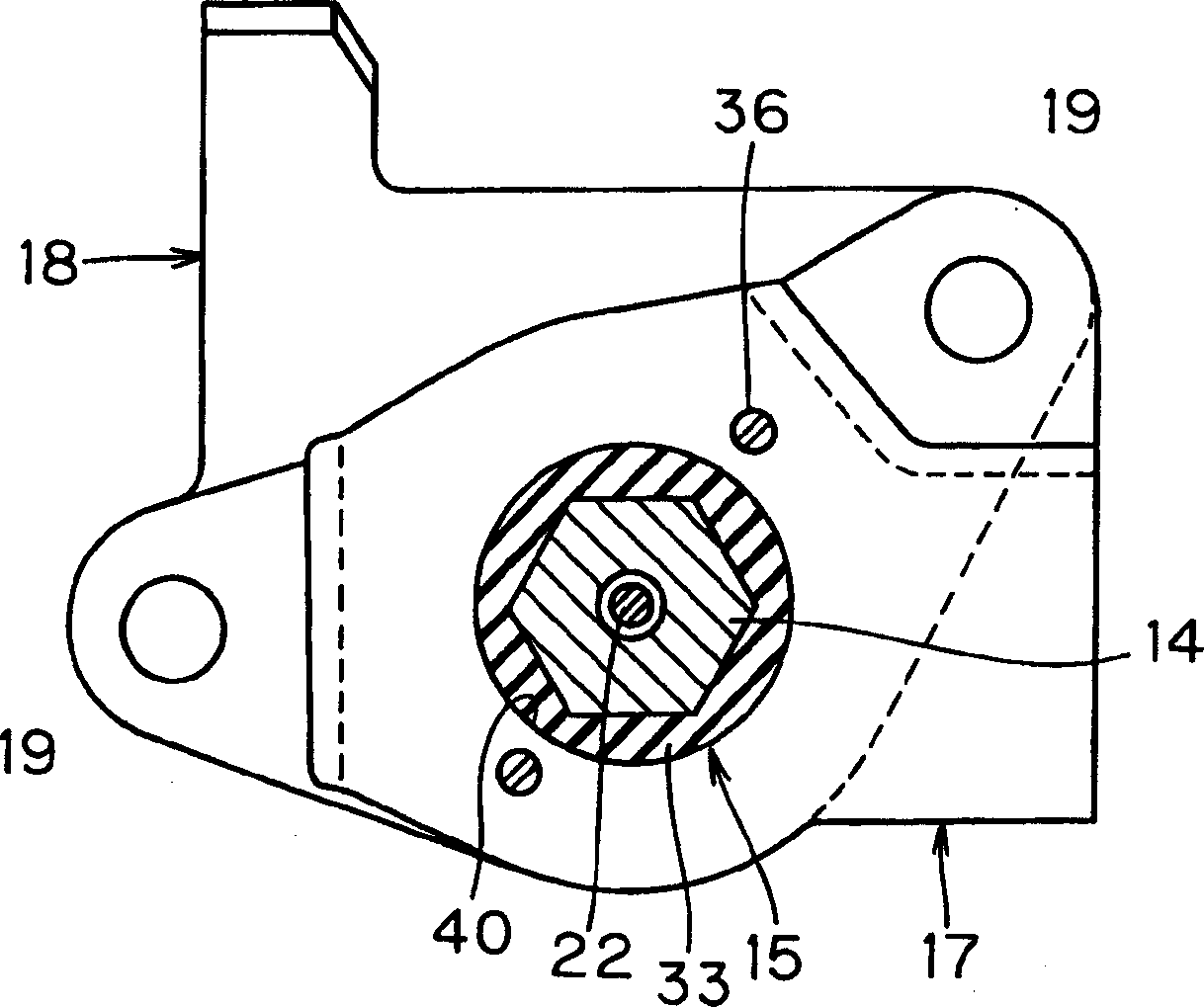
The terminal support device 10 is equipped with a casing cap 14 which has a conduit pipe fixing part 12 at one end and a flange 13 at the central part 14a, a pair of ring shaped dampers 15, 16 which are arranged so as to abut to both sides of the flange 13 at the outer periphery of the casing cap, and a first holding plate 17 and a second holding plate 18 which press to hold these dampers to the flange 13 side so as not to restraint their periphery.

Description

technical field [0001] This invention relates to end supports for steering cables. In more detail, it relates to an end support device with a vibration-proof structure, which is suitable for supporting the end of the engine room side of the push-pull operating cable (hereinafter referred to as AT cable) for automatic transmission operation, so that vibration is difficult to transmit to the gear lever. side. Background technique [0002] Generally, the end support device of the AT cable is installed on the upper side of the transmission strut or bracket in the engine room (refer to Figure 8 ), but in order to prevent the vibration in the engine room from being transmitted to the shift lever side as much as possible, a rubber-mounted housing cover is used to hold the end of the operating cable. for example Figure 11 The shown end support device 100 is composed of a housing cover 102 , anti-vibration rubber 104 , and housings 105 and 106 . The housing cover 102 is riveted ...

Claims


Application Information

Patent Timeline
Patent Type & Authority Applications(China)
IPC IPC(8): F16C1/10F16C1/26
Inventor 米真一安部秀和石川隆
Owner NIPPON CABLE SYSTEM INC
Learn More