
Fuel shooting valve

A fuel injection valve and fuel technology, which is applied to fuel injection devices, charging systems, engine components, etc., can solve problems such as discreteness, and achieve the effect of ensuring reliability, stable cooling effect, and reducing solids difference.

Inactive Publication Date: 2004-03-10
BOSCH AUTOMOTIVE SYST CORP
View PDF0 Cites 1 Cited by
  • Summary
  • Abstract
  • Description
  • Claims
  • Application Information

AI Technical Summary

Problems solved by technology

[0037] In this way, the performance of the fuel injection valve 1, that is, the assembly of its armature 21 and magnet core 23, that is, the injection quantity characteristics with respect to the energization time of the magnet 22, or the back pressure caused by the back pressure control unit 7 may affect its performance. Sensitivity, creating discrete issues between fuel injection valves 1

Method used


Image

  • Fuel shooting valve
  • Fuel shooting valve
  • Fuel shooting valve

Examples


Embodiment Construction

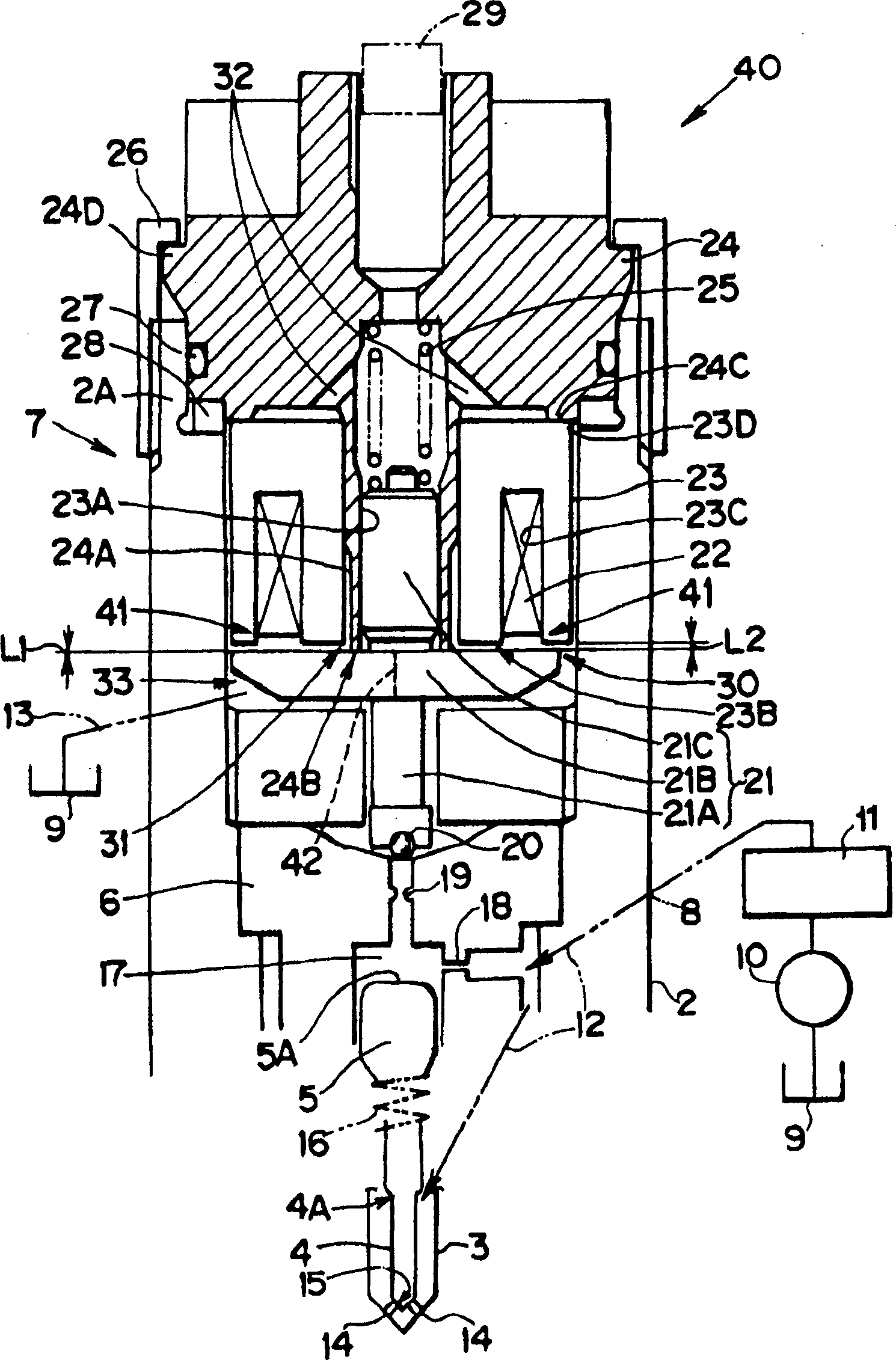
[0063] Below, according to figure 1 Embodiments of the present invention will be described in detail through FIG. 4 . and Figure 8 ~ Figure 11 The same symbols are assigned to the same parts, and detailed description thereof will be omitted here.

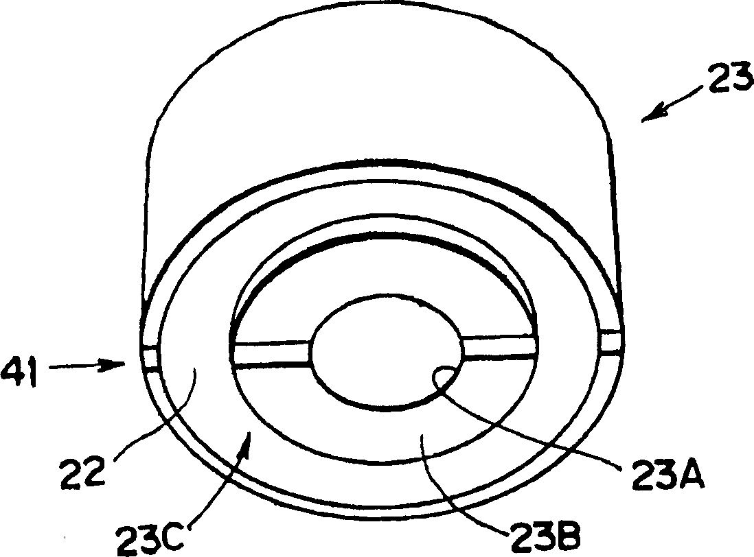
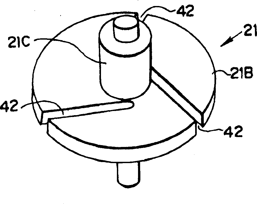
[0064] figure 1 is an enlarged sectional view of the main part of the fuel injection valve 40, figure 2 is a perspective view seen particularly from the attraction surface 23B side of the magnet core 23 in the fuel injection valve 40, image 3 is a perspective view of the armature 21, in the fuel injection valve 40, the configuration of the mutually opposing parts of the magnet core 23 and the armature 21 is the same as that of the already described fuel injection valve 1 ( Figure 8 ) are different.

[0065] especially if figure 2 As shown, a magnetic core radial gap 41 (radial gap) in the radial direction is formed on the side of the surface of the magnetic core 23 facing the armature 21 (attraction surface 23B side), an...


PUM


Abstract

To provide a fuel injection valve, establishing the relatively crossing condition of slits 41, 42 of a magnet core 23 and an armature 21 without fail, securing a uniform passage area on the opposed faces of the armature 21 and the magnet core 23 even in the different assembled conditions, and preventing the dispersion of the property of an injection amount or the sensitivity of back pressure. It is noted that the radial slit 41 is formed in the magnet core 23 and the radially shifted slit 42 is formed in the armature 21. The magnet core 23 is opposed to the armature 21 at a slight gap for attracting it. The radial slit 41 is formed in the magnet core 23 in the direction of its diameter and the radially shifted slit 42 is formed in the armature 21 in opposition to the radial slit 41. The radially shifted slit 42 and the radial slit 41 can cross each other.

Description

technical field [0001] The present invention relates to a fuel injection valve, and more particularly, to a fuel injection valve that injects high-pressure fuel supplied from a common-rail or the like within a predetermined time period. Background technique [0002] according to Figure 8 ~ Figure 11 A conventional fuel injection valve will be roughly described. [0003] Figure 8 It is an enlarged sectional view of the main part of the fuel injection valve 1 , which has an injector housing 2 , a nozzle body 3 , a nozzle needle 4 , a valve piston 5 , a valve body 6 and a back pressure control unit 7 . [0004] The injector housing 2 is provided with a nozzle body 3 at its front end, and a high-pressure fuel introduction part 8 is provided above it. The above-mentioned back pressure control unit 7 is also provided above the high-pressure fuel introduction unit 8 . [0005] The fuel from the fuel tank 9 is brought into a high-pressure state by the fuel pump 10 and stored in...

Claims


Application Information

Patent Timeline
IPC IPC(8): F02M47/00F02M47/02F02M51/00F02M51/06
CPCF02M47/027F02M51/061
Inventor 久保贤一野崎浩明
Owner BOSCH AUTOMOTIVE SYST CORP
Learn More