


Quick Research
Generate reliable direction feasibility study reports for your R&D in just a few steps.

Technical Q&A
Discover and master advanced knowledge NOW. Basics, ideas, possibilities, all at once.

Find Solutions
As an expert in R&D theories, this can generate solutions to your technical problems instantly.

Evaluate Feasibility
Analyze your overall solution with one click, know your potential R&D risks in advance.

Monitor Landscape
Get weekly tech updates, stay abreast of the latest tech innovations and key insights.
Injecting systems
A technology of injection system and syringe, applied in the field of injection system, can solve problems such as failure to monitor automatic jelly injection and failure to detect faults in time
- Summary
- Abstract
- Description
- Claims
- Application Information
AI Technical Summary
Problems solved by technology
Method used
Image

Examples
Embodiment Construction
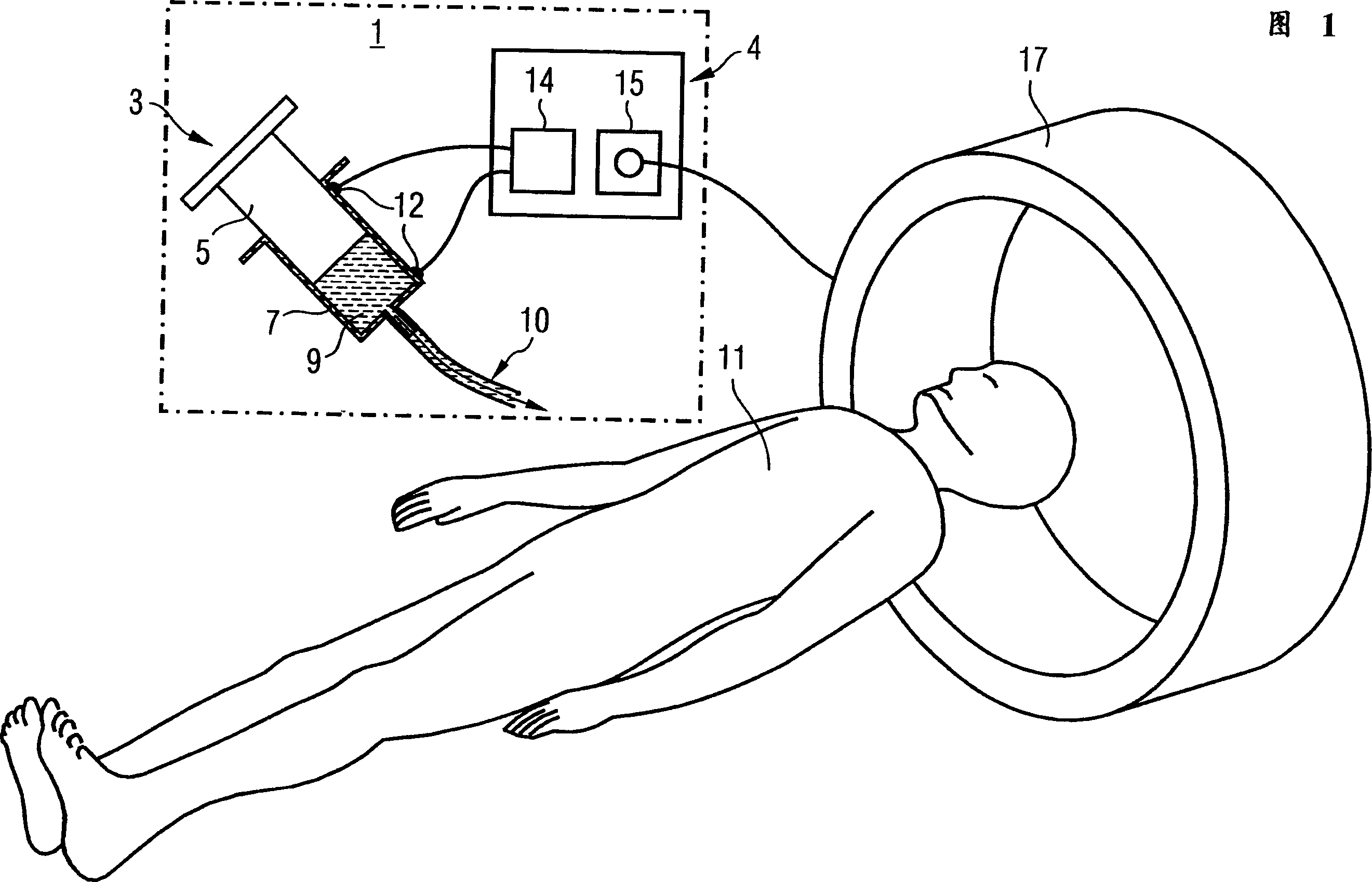
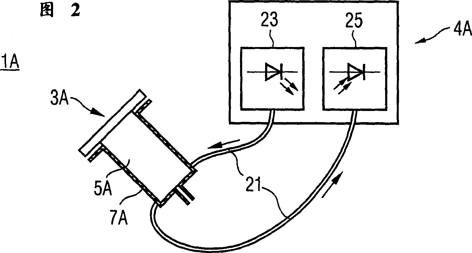
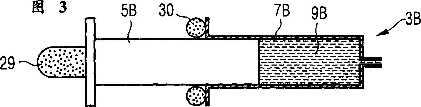
[0031] Figure 1 depicts an injection system 1 for the controlled injection of a substance 9, preferably a solvent for X-ray contrast, for radiological examinations. The injection system comprises a hand-operated injector 3 and a control unit 4 . The injector 3 is an injection syringe composed of a plunger 5 and a sleeve 7 .
[0032] The substance 9 to be injected is located in a volume (reservoir) formed by the plunger and the sleeve of the syringe 3 . The substance is injected intravenously through catheter 10 into patient 11 by pushing plunger 5 into sleeve 7 . The position of the plunger 5 thus determines the filling state of the cavity. A switch 12 is respectively fixed on the two travel points of the sleeve 7 of the syringe 3, and the switches are respectively connected with the control unit 4, and notify the control unit 4 that the plunger 5 has reached one of the two travel points and the cavity corresponding filling conditions. The switch 12 may for example be a ma...
PUM
 Abstract
Description
Claims
Application Information
 - R&D Engineer
- R&D Manager
- IP Professional
- Industry Leading Data Capabilities
- Powerful AI technology
- Patent DNA Extraction
Browse by: Latest US Patents, China's latest patents, Technical Efficacy Thesaurus, Application Domain, Technology Topic, Popular Technical Reports.
© 2024 PatSnap. All rights reserved.Legal|Privacy policy|Modern Slavery Act Transparency Statement|Sitemap|About US| Contact US: help@patsnap.com