
Microwave oven

A technology of microwave ovens and magnetrons, applied in the field of microwave ovens, can solve the problems of high cost and achieve the effect of low cost

Inactive Publication Date: 2004-01-28
KK TOSHIBA
View PDF0 Cites 3 Cited by
  • Summary
  • Abstract
  • Description
  • Claims
  • Application Information

AI Technical Summary

Problems solved by technology

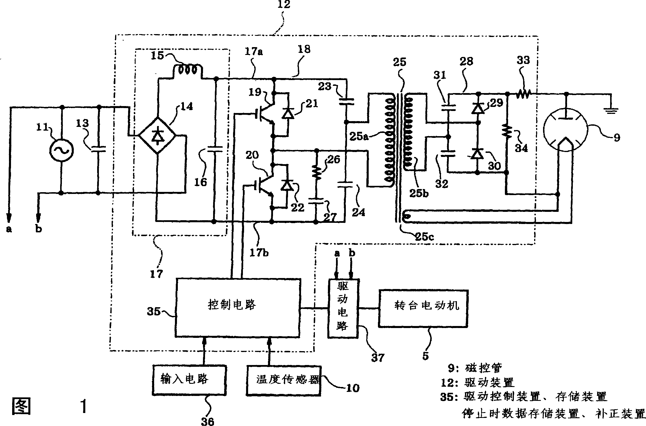
[0006] However, in such an existing structure, detection devices such as the current detection device 108 must be provided, so there is a disadvantage of high cost (cost overrun)

Method used


Image

  • Microwave oven
  • Microwave oven
  • Microwave oven

Examples


Embodiment Construction

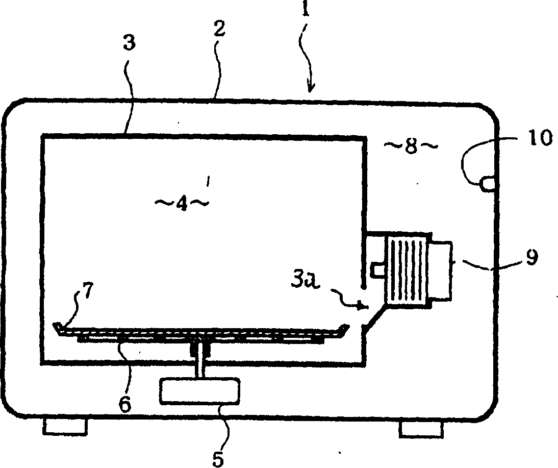
[0024] Below, refer to Figure 1 to Figure 5 An embodiment of the present invention will be described. First, in figure 2 Among them, a main body 1 of a microwave oven is composed of an outer case 2 and an inner case 3 , and the interior of the inner case 3 constitutes a heating chamber 4 . A turntable motor (turntable motor) 5 is disposed on the outer bottom of the heating chamber 4 , and its rotating shaft protrudes inside the heating chamber 4 , and is connected to a rotary net 6 . A detachable rotary disk 7 is arranged on the rotary net 6 . A space between the right side plate of the inner case 3 and the right side plate of the outer case 2 constitutes a machine room 8 . In the machine room 8, a magnetron 9 is mounted on the right side plate of the inner box 3, and microwaves (microwaves) generated by the magnetron 9 are supplied into the heating chamber 4 from the excitation port 3a. In addition, a temperature sensor 10 for detecting the temperature of outside air is...


PUM


Abstract

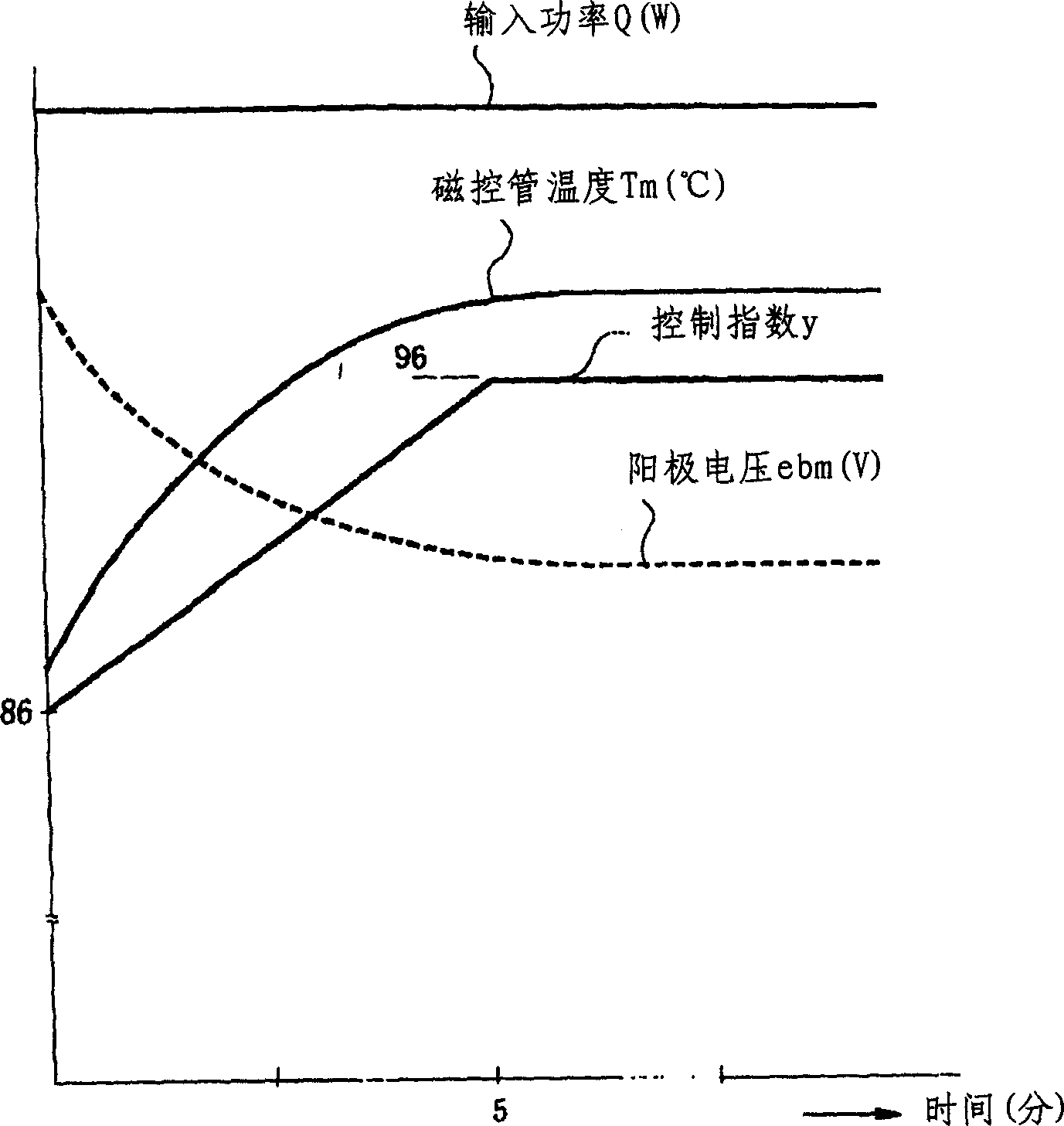
The present invention provides a microwave oven for controling the input power with a simple structure. The magnetron is driven by a drive circuit comprising a control circuit for controlling the drive circuit to control an input power of the magnetron. The controlling circuit has a ROM for recording a control index and controls the drive circuit according to the control index such that the input power of the magnetron is controlled to be constant.

Description

technical field [0001] The present invention relates to a microwave oven that performs input power control of a magnetron. Background technique [0002] Image 6 The circuit of a conventional microwave oven, especially the drive circuit of the magnetron 100 is shown. A magnetron drive circuit 102 is connected to the AC power supply 101 , and the drive circuit 102 is composed of a DC power supply circuit 103 , an inverter circuit 104 , a high frequency transformer (high frequency transformer) 105 and a voltage doubler rectification circuit 106 . [0003] In the above structure, the converter circuit 104 includes switching elements (switching elements) 104a, 104b, and the switching elements 104a, 104b are controlled by the control circuit 107 to switch (on, off). Then, a high-frequency current is generated on the primary winding (primary winding) 105a of the high-frequency transformer 105 by this switching operation, and voltage doubler rectification power is generated on the...

Claims


Application Information

Patent Timeline
Patent Type & Authority Applications(China)
IPC IPC(8): H05B6/68F24C7/02F24C7/08
CPCE02B3/14E02D29/0283E02D2600/20
Inventor 岡部眞澄
Owner KK TOSHIBA
Learn More