
Dust absorption head for electric vacuum cleaner and electric vacuum cleaner

A vacuum cleaner and vacuum head technology, applied in vacuum cleaners, suction nozzles, applications, etc., can solve the problem that the dust collection range of the floor suction head 210 becomes smaller, the floor suction head 210 cannot successfully complete the dust collection, and the suction head with a brush 250 angle instability and other issues

Inactive Publication Date: 2003-12-10
PANASONIC CORP
View PDF1 Cites 12 Cited by
  • Summary
  • Abstract
  • Description
  • Claims
  • Application Information

AI Technical Summary

Problems solved by technology

[0005] However, when the above-mentioned existing electric vacuum cleaner uses the floor suction head 210, the height of the dust suction head part is very high, so that the floor suction head 210 cannot be stretched in such a place where the space height is low, so there is a problem that the floor suction head 210 can absorb dust. The problem of narrowing the range
[0006] In addition, since the ball joint 240 is in the vertical direction of the floor suction head 210, and the extension tube 213 is connected obliquely above the ball joint 240, when it is desired to change the direction of the floor suction head 210 by operating (turning) the handle, even if the rotation lengthens The pipe 213 and the floor suction head 210 are not easy to rotate in the direction to be switched, and there is a problem that the floor suction head 210 cannot be used to clean the dust smoothly
[0007] In addition, since the cleaning head with brush 250 is connected by the ball joint 240 that can rotate in the rotation direction and the vertical direction, when the cleaning head with brush 250 is separated from the floor suction head 210, only the cleaning head with brush can be used. When the 250 is vacuuming, there is a problem that the angle of the suction head 250 with a brush is unstable and the vacuuming operation is difficult

Method used


Image

  • Dust absorption head for electric vacuum cleaner and electric vacuum cleaner
  • Dust absorption head for electric vacuum cleaner and electric vacuum cleaner
  • Dust absorption head for electric vacuum cleaner and electric vacuum cleaner

Examples


Embodiment Construction

[0032] Next, a first embodiment of the present invention will be described with reference to the drawings. It should be noted that the following embodiment is only an example of embodying the present invention, and the scope of rights of the present invention is not limited thereto.

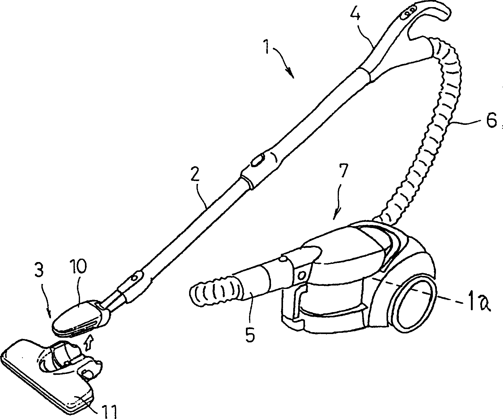
[0033] This example figure 1 As shown in , the figure shows a ground mobile electric vacuum cleaner 1 and a dust suction head 3 as its dust suction device. The structure of this electric vacuum cleaner 1 is as follows. The dust suction head 3 is mounted on the front end of the extension tube 2 in a detachable manner, the extension tube 2 is connected with the handle (hand lever) 4, and the hose 6 extending from the handle 4 passes through the hose connector 5 and The vacuum cleaner main body 7 is connected. An electric blower 1a is provided inside the main body 7 of the vacuum cleaner.

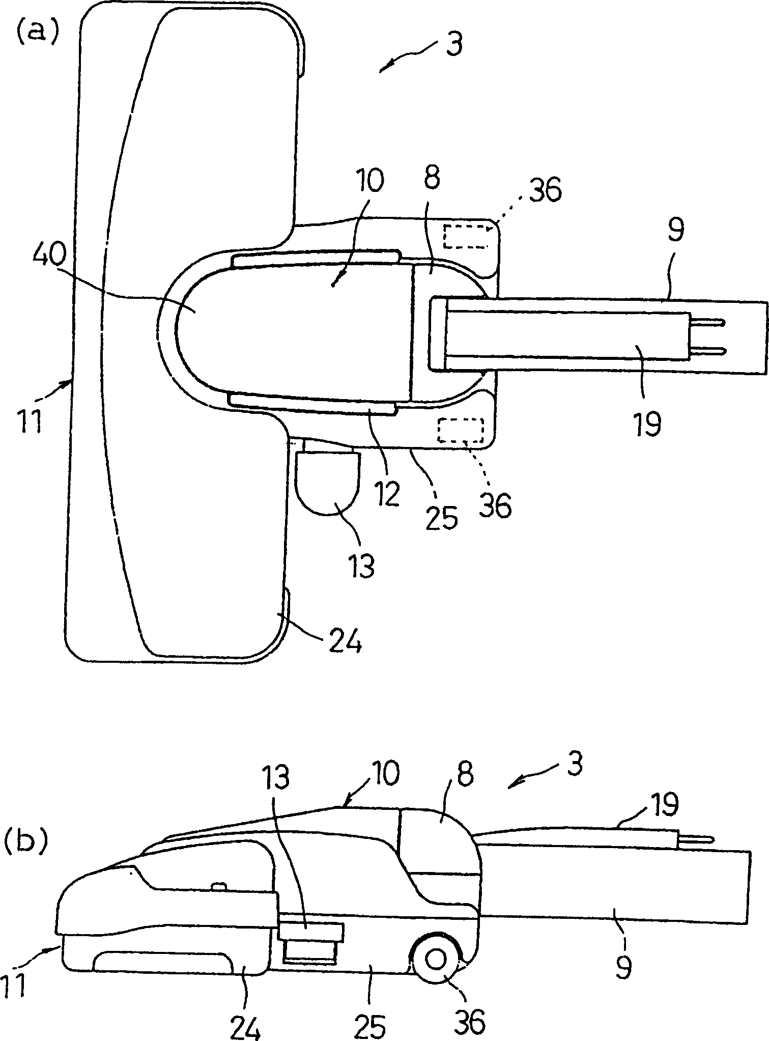
[0034] Above-mentioned suction head 3 such as figure 2 (a) and (b) are composed of a small suction head...


PUM


Abstract

A suction nozzle for use in a vacuum cleaner includes a floor nozzle (11) and a mini nozzle (10) having a suction head (40), a rotatable joint (8), and joint (9), to be detachably secured in the floor nozzle (11). Either of the suction head (40) and the rotatable joint (8) or the rotatable joint (8) and the joint (9) is vertically joined and the other rotatably joined. Moreover, the suction head (40) is unrotatably secured onto the floor nozzle (11), and forms an air communication with the floor nozzle (11).

Description

technical field [0001] The invention relates to a suction head for an electric vacuum cleaner capable of freely switching between a floor suction head and a small suction head mounted on it in a detachable manner, and an electric vacuum cleaner. Background technique [0002] Figure 21 An example of a ground mobile electric vacuum cleaner is shown in , wherein the floor suction head 101 is mounted on the front end of the extension pipe 102 in a detachable manner, the extension pipe 102 is connected with the armrest handle 103, and the armrest handle 103 extends The hose 104 is connected to the main body 106 of the vacuum cleaner through a hose connecting pipe 105 . When using such an electric vacuum cleaner for vacuuming, the floor suction head 101 with a wider width can be used for cleaning the floor with high efficiency. place, the floor suction head 101 is not needed. Generally speaking, electric vacuum cleaners are equipped with supplementary suction heads such as gap ...

Claims


Application Information

Patent Timeline
Patent Type & Authority Applications(China)
IPC IPC(8): A47L9/02A47L9/06A47L9/24A47L9/28
CPCA47L9/066A47L9/02A47L9/2857A47L9/2805A47L9/0673A47L9/2842A47L9/06A47L9/242A47L9/062
Inventor 浦田裕之副岛雅邦藤田孝一澁谷昌树今井秀利高桥正樹福嶋雅一妹尾裕之
Owner PANASONIC CORP
Learn More