Split type optical fiber core
An optical fiber ribbon and split-type technology, applied in the field of split-type optical fiber ribbon core wires and their manufacturing, can solve the problems of cracking and difficult splitting of the connecting resin, and achieve the effect of excellent splitting.
- Summary
- Abstract
- Description
- Claims
- Application Information
AI Technical Summary
Problems solved by technology
Method used
Image


Examples
Embodiment 1
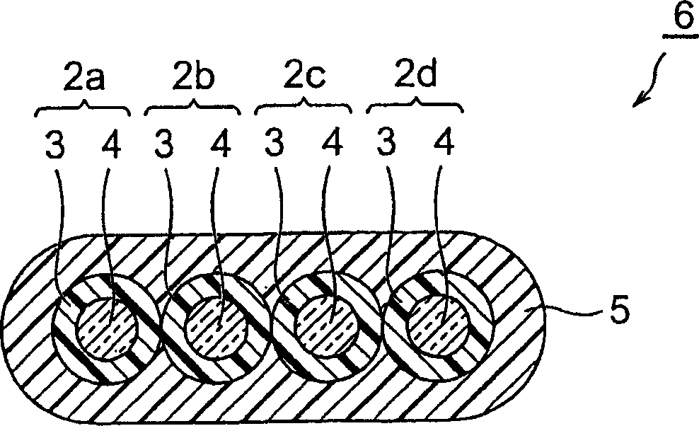
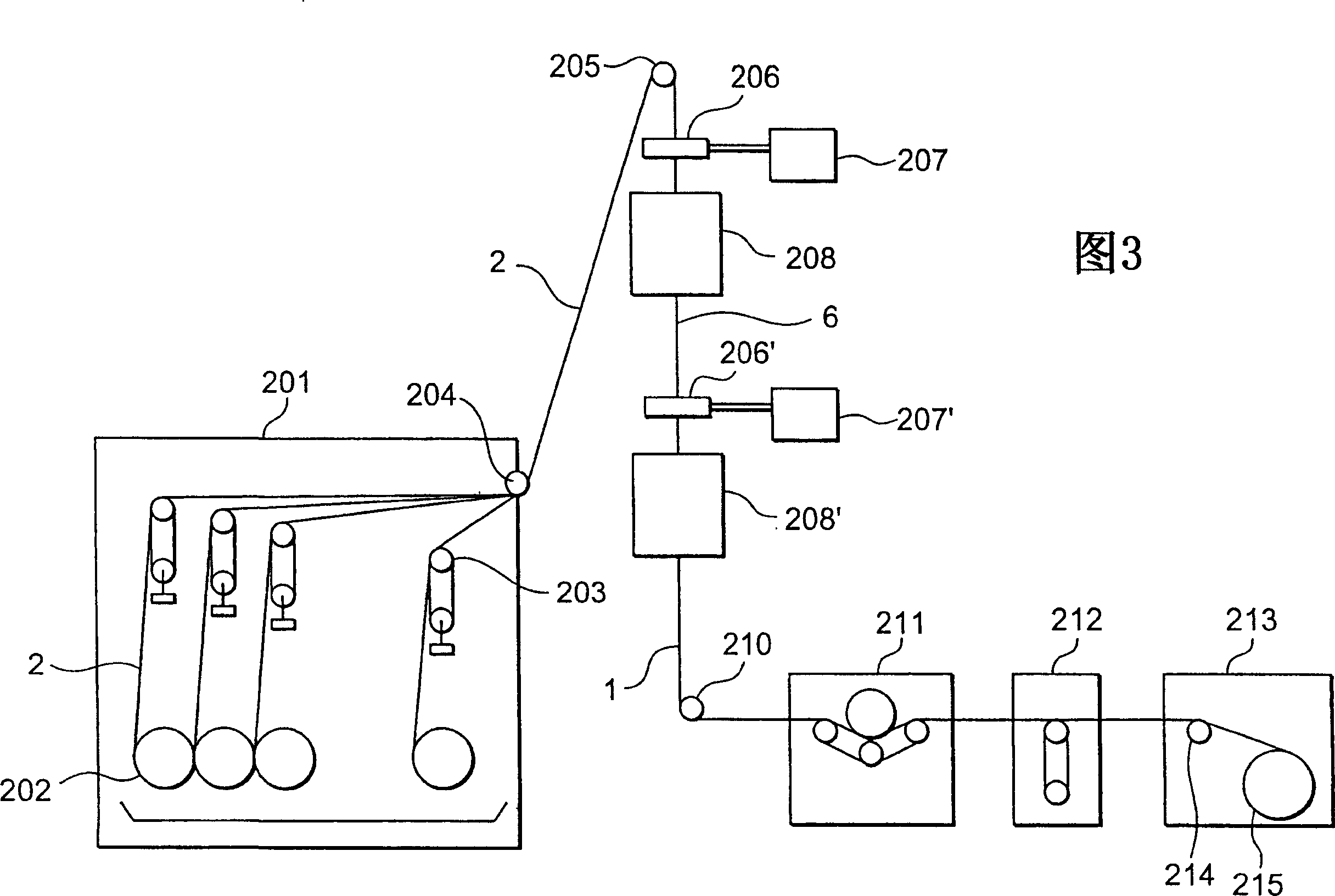
[0070] In the following order, use the figure 2 The apparatus shown produces a split-type optical fiber ribbon as shown in FIG. 1 . In the following examples, the curing of the ultraviolet curable resin composition was carried out under two conditions of high linear velocity (800 m / min) and low linear velocity (600 m / min).
[0071] (optical fiber core wire)
[0072] As the optical fiber core wire, an optical fiber colored core wire (outer diameter of 255 μm) can be used. The core wire is a single-mode glass optical fiber with an outer diameter of 125 μm coated twice with urethane acrylate resin, and then coated with a colorant. Formed by coating with urethane acrylate resin.
[0073] (Manufacturing of optical fiber ribbon core wire)
[0074] Arrange 4 above-mentioned optical fiber ribbons side by side, and coat the ultraviolet curable resin composition A having the following components on their periphery:
[0075] Urethane acrylic resin obtained by reacting 1 mol of diol a...
Embodiment 2
[0105] In addition to having the composition shown below:
[0106] Polytetramethylene glycol 1mol, the urethane acrylic resin obtained by the reaction of toluene diisocyanate 2mol and hydroxyethyl acrylate 2mol: 20 parts by weight
[0107] Lauryl acrylate; 15 parts by weight
[0108] Bisphenol A epoxy diacrylate: 45 parts by weight
[0109] Nonylphenyl acrylate added with ethylene oxide: 15 parts by weight
[0110] 2-Methyl-1-[4-(methylthio)phenyl]-2-morpholino-propan-1-one (Irgacure907, manufactured by Chiba Special Chemicals Co., Ltd.): 2 parts by weight
[0111] 2,4,6-trimethylbenzoyldiphenylphosphine oxide (Lucilin TPO, manufactured by BASF): 3 parts by weight
[0112] A split-type optical fiber ribbon having the structure shown in FIG. 1 was produced in the same manner as in Example 1 except that the ultraviolet-curable resin composition C was used instead of the ultraviolet-curable resin composition B. In the ultraviolet curable resin composition C, the concentration...
Embodiment 3
[0129] In a nitrogen atmosphere, the ultraviolet curable resin composition A was coated on the support, and the UV curable resin composition A was irradiated with ultraviolet light (irradiation light amount: 100mJ / cm 2 ) was irradiated to make it solidify, and a thin film with a film thickness of 100 μm was produced, and its Young's modulus was measured. The results obtained are shown in Table 1. In addition, the measured Young's modulus and the 500mJ / cm 2 The ratio of the Young's modulus (500mJ ratio) obtained when it is cured by ultraviolet radiation is used as an index of curing speed. When 500mJ is relatively large, it means that the curing speed is fast.
[0130] (curing performance experiment 2)
[0131] Further, the film obtained in curability experiment 1 was extracted with methyl ethyl ketone at 60° C. for 16 hours. And determine the ratio of its gel components. The results obtained are shown in Table 1. The ratio of the gel component is an indicator of the amou...
PUM
 Abstract
Description
Claims
Application Information
 - R&D
- Intellectual Property
- Life Sciences
- Materials
- Tech Scout
- Unparalleled Data Quality
- Higher Quality Content
- 60% Fewer Hallucinations
Browse by: Latest US Patents, China's latest patents, Technical Efficacy Thesaurus, Application Domain, Technology Topic, Popular Technical Reports.
© 2025 PatSnap. All rights reserved.Legal|Privacy policy|Modern Slavery Act Transparency Statement|Sitemap|About US| Contact US: help@patsnap.com