Liquid crystal display device
A technology of a liquid crystal display device and a liquid crystal display panel, which is applied in the field of front-lit liquid crystal display devices, and can solve the problems of decreased brightness, worsened brightness consistency, and increased cost of liquid crystal display devices, etc.
- Summary
- Abstract
- Description
- Claims
- Application Information
AI Technical Summary
Problems solved by technology
Method used
Image

Examples
no. 1 example
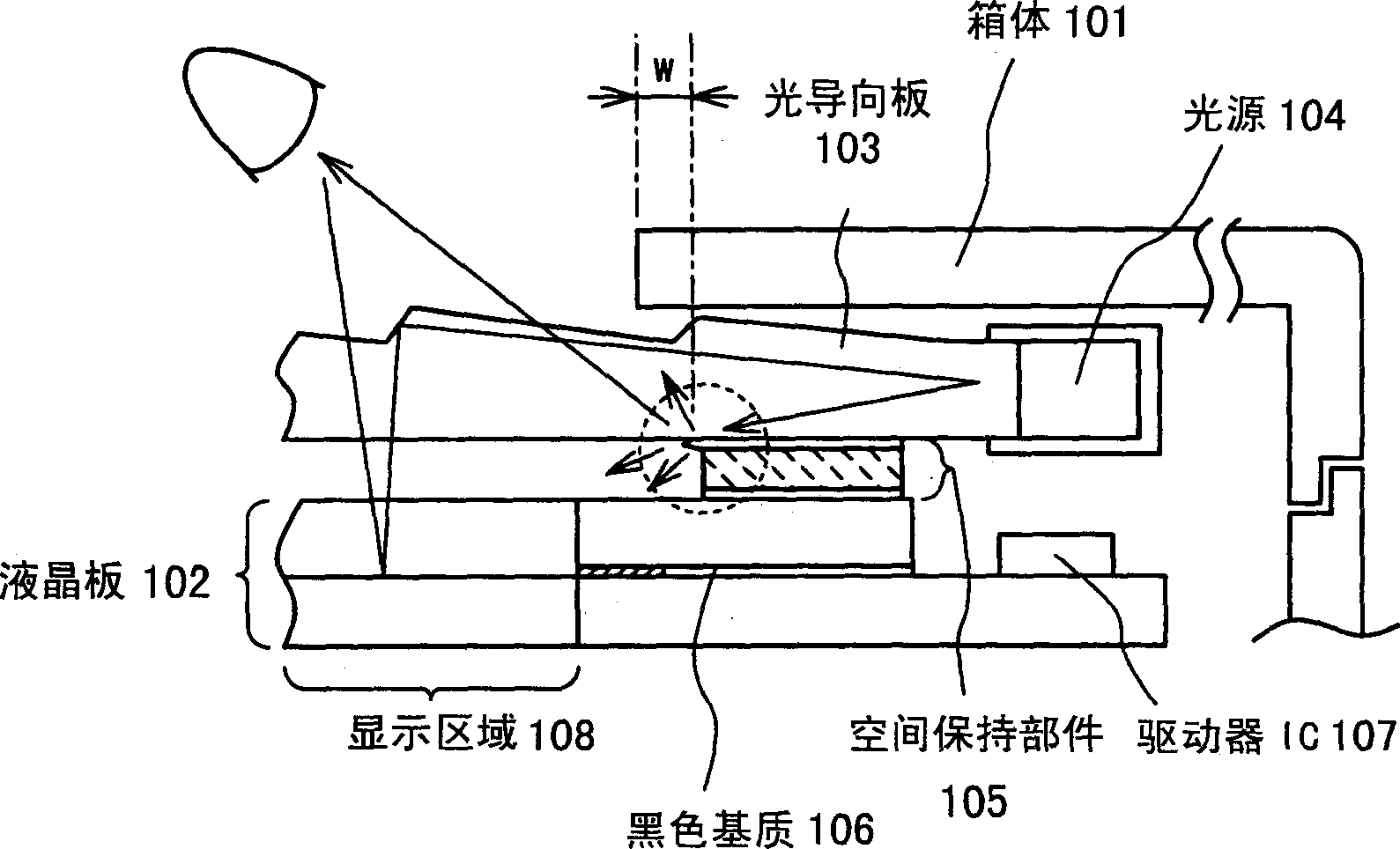
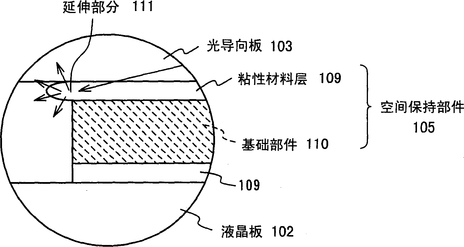
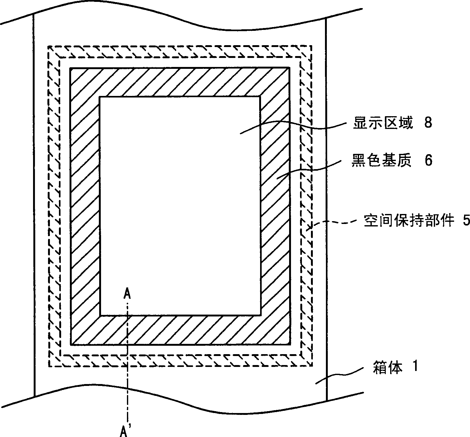
[0048] First, refer to figure 2 , Figure 3A and Figure 3B A liquid crystal display device according to the frontlight method of the first embodiment of the present invention is described below. figure 2 is a plan view showing the structure of a display portion of a liquid crystal display device of a frontlight method according to a first embodiment of the present invention. same, Figure 3A is shown along figure 2 A cross-sectional view of the end of the display area of the liquid crystal display device on line A-A, and Figure 3B yes Figure 3A An expanded view of the portion of the display area surrounded by a circle in .
[0049] The liquid crystal display device in the first embodiment mainly includes a cabinet 1 , a liquid crystal display panel 2 , a light guide plate 3 , a light source 4 and a space maintaining member 5 . In the liquid crystal display panel 2, liquid crystals are placed between opposing substrates. A light source 4 is provided in the side ...
no. 3 example
[0064] Next, we will refer to Figure 5 , Figure 6A , Figure 6B , Figure 7A and Figure 7B A liquid crystal display device according to the frontlight method of the third embodiment of the present invention will be described. Figure 5 is a plan view showing the structure of the display portion of the liquid crystal display device of the frontlight method in the third embodiment. Figure 6A and Figure 7A is shown along Figure 5 Line B-B in shows a cross-sectional view near the end portion of the region. Figure 6B and Figure 7B yes Figure 6A and Figure 7A The expanded view of the circled part in the middle.
[0065] In a second embodiment, light absorbing material is distributed and mixed in a layer of adhesive material. However, instead of using a light absorbing adhesive material, a layer of light shielding material may be arranged to cover the area of the light guide plate 3 corresponding to the space maintaining member 5 . The light shielding material...
no. 4 example
[0068] Next, we will refer to Figure 8A and Figure 8B A liquid crystal display device according to a frontlight method according to a fourth embodiment of the present invention will be described. Figure 8A is a cross-sectional view showing the structure of the end of the display region of the liquid crystal display device of the frontlight method in the first to third embodiments. Figure 8B is a cross-sectional view showing the structure of the end of the display region of the liquid crystal display device of the front light method in the fourth embodiment.
[0069] In the first to third embodiments, a structure in which an adhesive material or a light shielding material which itself has a refractive index and contains a compound is provided between the space maintaining member 5 and the light guide plate 3 is used. However, in addition to the light incident directly from the light source 4, there is light reflected approximately vertically from the surface of the liquid...
PUM
| Property | Measurement | Unit |
|---|---|---|
| refractive index | aaaaa | aaaaa |
| refractive index | aaaaa | aaaaa |
| refractive index | aaaaa | aaaaa |
Abstract
Description
Claims
Application Information
 - R&D
- Intellectual Property
- Life Sciences
- Materials
- Tech Scout
- Unparalleled Data Quality
- Higher Quality Content
- 60% Fewer Hallucinations
Browse by: Latest US Patents, China's latest patents, Technical Efficacy Thesaurus, Application Domain, Technology Topic, Popular Technical Reports.
© 2025 PatSnap. All rights reserved.Legal|Privacy policy|Modern Slavery Act Transparency Statement|Sitemap|About US| Contact US: help@patsnap.com