Exosure method and device

An exposure method and exposure device technology, applied in optics, optomechanical equipment, nonlinear optics, etc., can solve the problem that patterns cannot be superimposed on a predetermined position with good precision

Active Publication Date: 2003-09-24
NIKON CORP
View PDF2 Cites 2 Cited by
  • Summary
  • Abstract
  • Description
  • Claims
  • Application Information

AI Technical Summary

Problems solved by technology

[0010] In this way, when the target correction amount deviates from the actual correction amount, there is a problem that the next pattern cannot be superimposed on the predetermined positional relationship with good accuracy for the pattern already formed on the substrate.

Method used


Image

  • Exosure method and device
  • Exosure method and device
  • Exosure method and device

Examples


Embodiment Construction

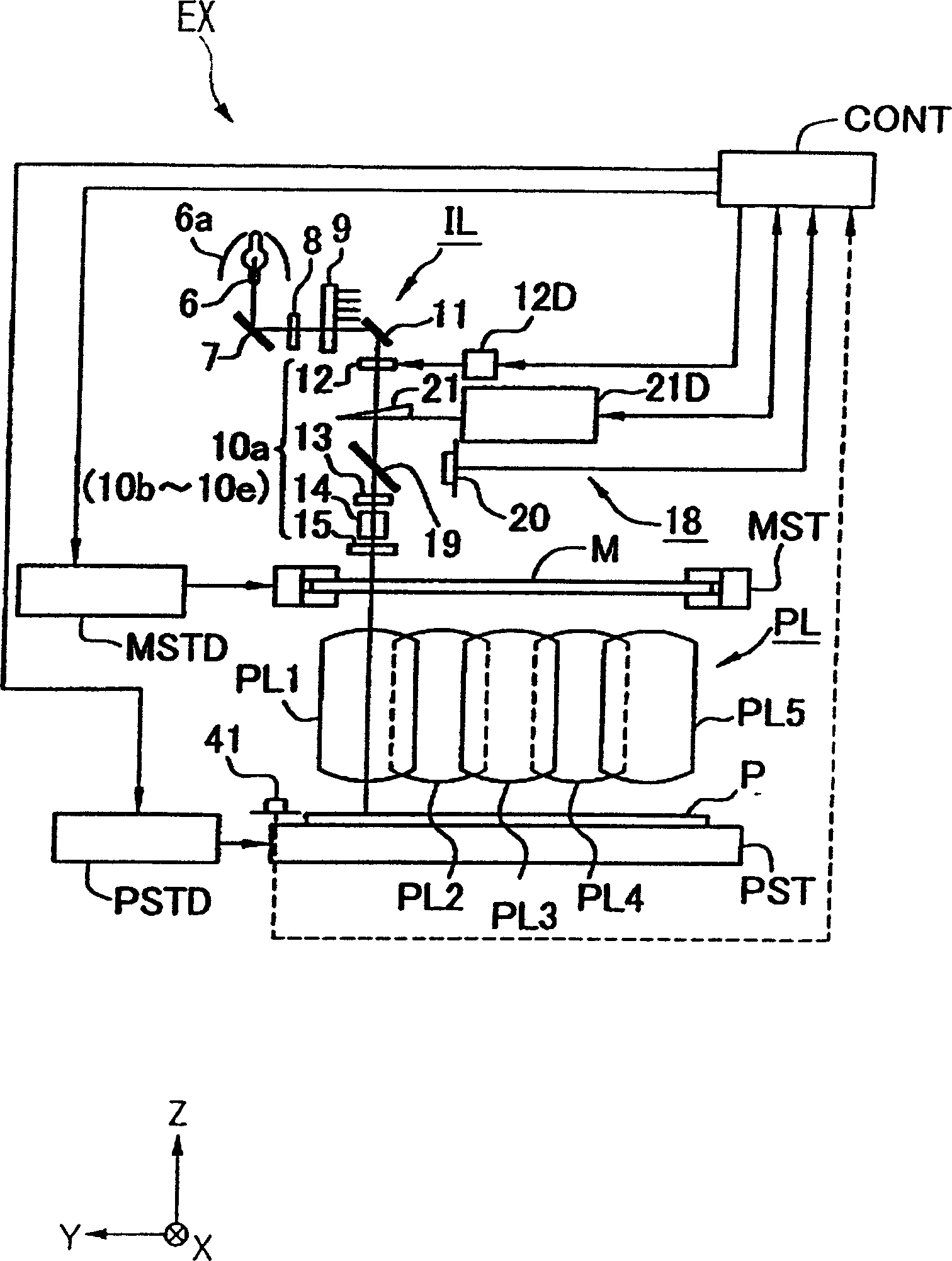
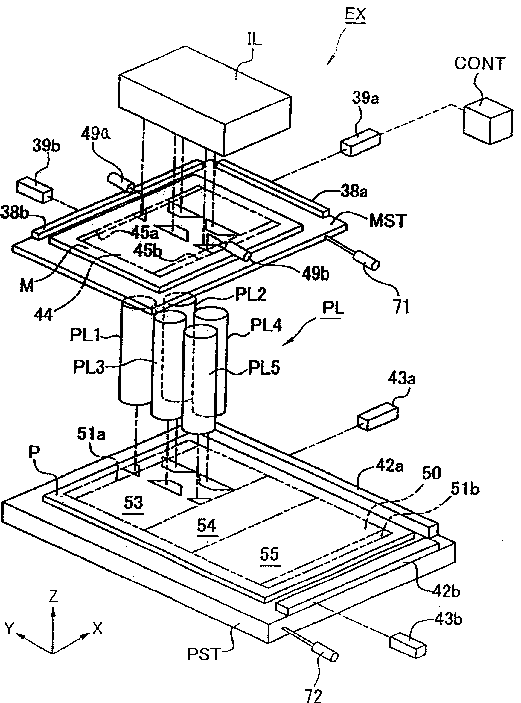
[0046] Hereinafter, the exposure method and exposure apparatus of this invention are demonstrated, referring drawings. figure 1 A schematic configuration diagram showing an embodiment of the exposure apparatus of the present invention, figure 2 for figure 1 rough oblique view of .

[0047] exist figure 1 and figure 2 The exposure apparatus EX includes an illumination optical system IL, a mask machine MST, a plurality of projection optical systems PL1 to P5, a substrate machine PST, mask side laser interferometers 39a, 39b, and substrate side laser interferometers 39a, 39b. Among these, illumination optical system IL has several illumination system elements (Module) 10a-10e which illuminate mask M with exposure light. The mask station MST supports the mask M. Several projection optical systems PL1-PL5 are arrange|positioned so that it may correspond to each illumination system element 10a-10e, and project the image of the pattern of the mask M illuminated with exposur...


PUM


Abstract

An exposure device is provided. In an exposure device EX, a mask M and a sensitive plate P move synchronously and a pattern of the mask M is projected onto the sensitive plate P through projection optical systems PL1 - PL5. The exposure device EX comprises the projection optical systems PL1 - PL5, a correction mechanism, a driving device and a control device CONT. The correction mechanism is disposed in the projection optical systems PL1 - PL5 for correcting an image property of the pattern projected on the sensitive plate P. The driving device is used to drive the correction device. The control device CONT sets one of a driving speed and a driving amount to the driving device according to a synchronous moving speed. Therefore, when correcting an image property and scanning and exposing, the pattern can be accurately overlapped at a pre-determined position by performing an accurate correction. As a result, the exposure device performs an accurate exposure process.

Description

technical field [0001] The present invention relates to an exposure method and an exposure device, in particular to a scanning exposure method and an exposure device for exposing a pattern of the mask to the substrate while moving a mask and a substrate synchronously. Background technique [0002] Electronic components such as liquid crystal display elements and semiconductor elements are manufactured by transferring the pattern formed on the photomask onto a photosensitive substrate by so-called lithography. The exposure device used in this lithographic etching process includes a photomask stage and a substrate stage. The photomask stage carries a photomask with a pattern and moves in two dimensions, and the substrate stage carries a photosensitive stage. The substrate moves in a two-dimensional manner, so that the pattern formed on the mask is projected and exposed on the photosensitive substrate by moving the mask machine and the plate machine successively through the pro...

Claims


Application Information

Patent Timeline
IPC IPC(8): G03F7/22G02F1/13G03F9/00H01L21/027
CPCG03F7/70358G03F9/7019G03F9/7088
Inventor 胜目智弘
Owner NIKON CORP
Why Eureka
Try Eureka