Eureka AIR delivers breakthrough ideas for toughest innovation challenges, trusted by R&D personnel around the world.

Vision testing system

A vision and target technology, applied in the field of lens-free vision testing, can solve problems such as expensive devices and lack of optometry services

Inactive Publication Date: 2003-08-27
AIVISION PTY LTD
View PDF0 Cites 39 Cited by
  • Summary
  • Abstract
  • Description
  • Claims
  • Application Information

AI Technical Summary

Problems solved by technology

Such devices are often quite expensive
People who are immobile or live far from cities or large towns are therefore disadvantageously lacking in optometry services
When an optometrist visits, usually only a few lenses are used for diagnostic purposes, and as such, the examination performed may not be as comprehensive as that performed with the typical devices mentioned above

Method used


Image

  • Vision testing system
  • Vision testing system
  • Vision testing system

Examples


Embodiment Construction

[0089] Vision tests in optometry clinics typically make extensive use of lenses. Disclosed herein is a vision analysis system that does not require the use of lenses. The absence of lenses is achieved by a computer-based vision testing system incorporating a program that allows vision testing to be performed on a video display unit, such as a computer monitor, and which can be performed at a location remote from the optometrist.

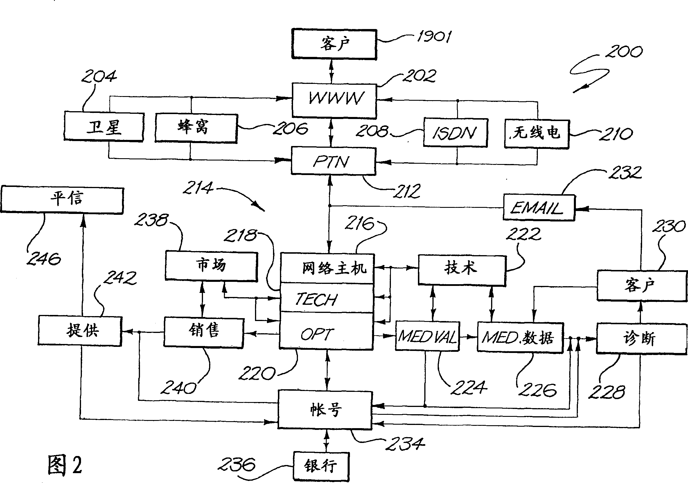
[0090] The remote vision test disclosed herein has two basic parts: vision test and vision diagnosis. Vision testing may be performed using a computerized remote vision testing device operated by the patient or an assistant. The computer is typically connected to a network, such as the World Wide Web (WWW), to allow access to other computers engaged in diagnostic evaluation.

[0091] The vision testing methods described herein preferably use a conventional general purpose computer system 1900, such as at Figure 19 2 to 18 may be implemented as so...


PUM


Abstract

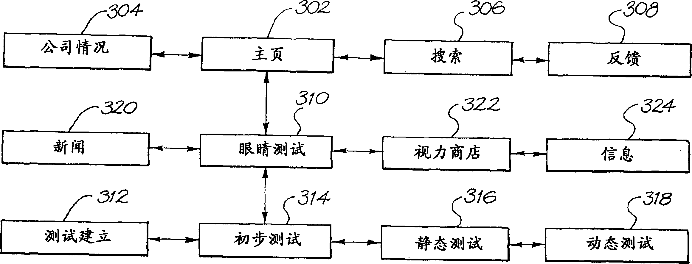
A method and apparatus are provided for testing the vision of a human subject using a series of eye tests (310). A test setup procedure (312) is run to adjust the settings of a display device (1914) such that graphic objects displayed on the device (1914) conform to a pre-defined appearance. A series of preliminary tests (314), static tests (316) and dynamic tests (318) are displayed on the device (1914), and the responses of the subject are recorded. The tests (310) may be run remotely, for example over the Internet. No lenses are required to run the tests (310).

Description

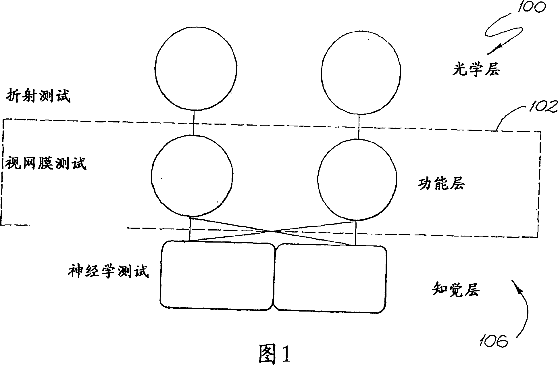
technical field [0001] The present invention relates generally to vision testing of subjects, and more particularly to lensless vision testing using a video display screen. Background technique [0002] Vision is intimately involved in almost every aspect of a person's daily life. If a person's vision is reduced, usually the person's quality of life is also reduced. [0003] Vision can be broken down into three conceptual layers, generally seen in Figure 1. The optical layer 100 provides focusing of light in the photosensitive layer of the tissue at the back of the eye called the retina. The functional layer 102 (formed by the retina) contains photoreceptor cells that can detect various colors, movements and forms and convert them into nerve impulses that are sent to the brain. The third layer is the perception layer 106, which is the part of the brain that makes images from the light information sent from the eyes. [0004] During the last century, many tests to measure...

Claims


Application Information

Patent Timeline
Patent Type & Authority Applications(China)
IPC IPC(8): A61B3/00A61B3/02A61B3/024A61B3/028A61B3/032A61B3/06A61B3/10A61B3/18G09G5/373
CPCA61B3/028A61B3/032
Inventor 戴西蒙德·J·马德林纳西蒙·格尔贝斯基
Owner AIVISION PTY LTD
Why Eureka
Eureka Blog
Learn More