Bistable device for reflection display with inverse contrast

A reflective, bistable display technology used in static indicators, nonlinear optics, instruments, etc.

Inactive Publication Date: 2003-07-09
NEMOPTIC
View PDF2 Cites 5 Cited by
  • Summary
  • Abstract
  • Description
  • Claims
  • Application Information

AI Technical Summary

Problems solved by technology

Unfortunately, it is difficult for the thickness d and T 0 The state twist angle Δφ is very sensitive to changes, both of which are unavoidable for technical reasons

Method used


Image

  • Bistable device for reflection display with inverse contrast
  • Bistable device for reflection display with inverse contrast
  • Bistable device for reflection display with inverse contrast

Examples


Embodiment Construction

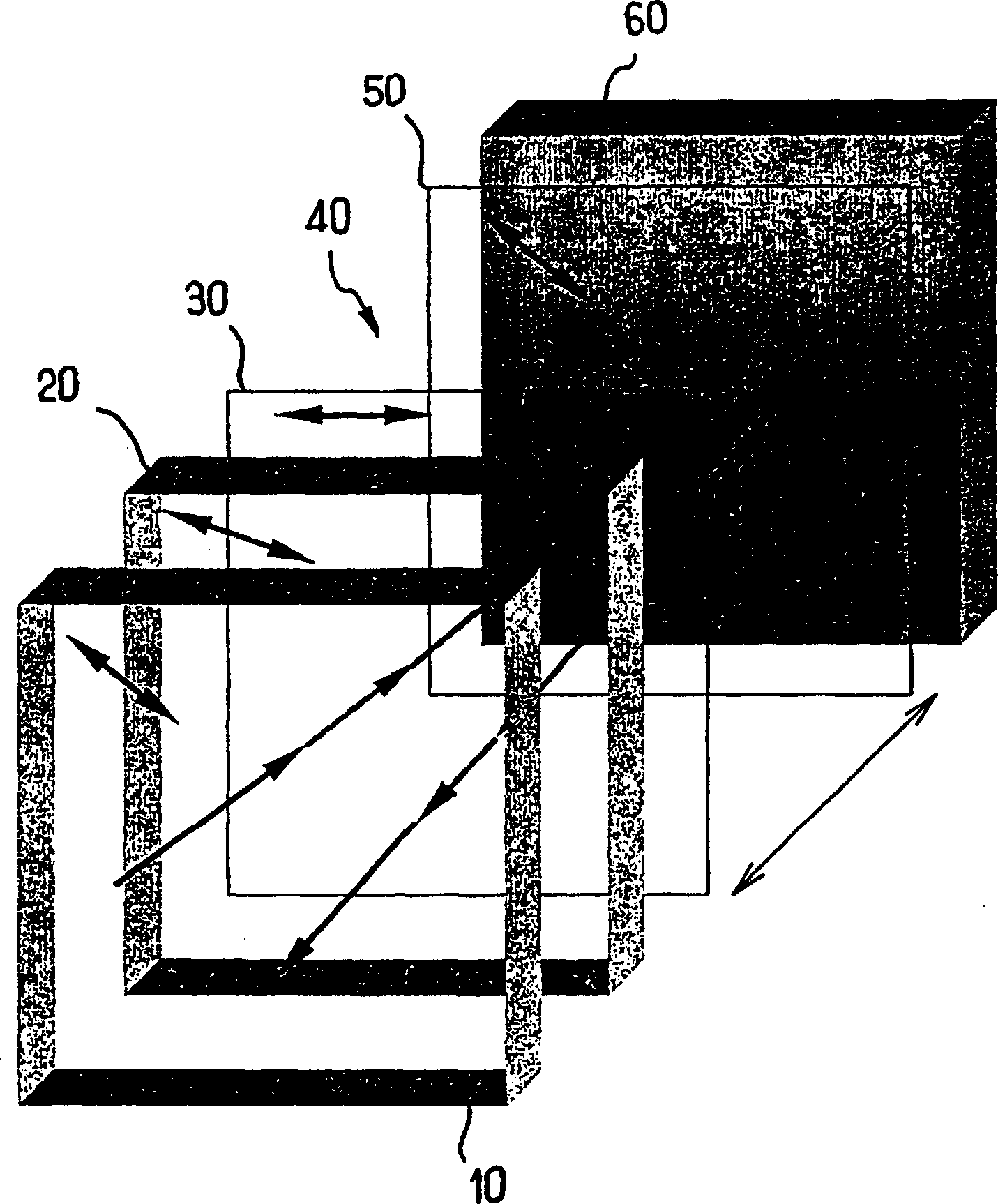
[0059] For other reflective displays, the bistable device can be made in various configurations, with one or two polarizers, one or two compensation plates, etc. In the present invention, the device has a single polarizer disposed in the optical path on the front surface of the device. This structure has the important advantage of maximizing brightness, since it minimizes light loss due to the possible presence of a second polarizer.

[0060] Such as image 3 As shown, the device of the present invention includes a device disposed between two substrates 30, 50 with a thickness of d A liquid crystal layer 40, preferably nematic liquid crystal; a polarizer 10 on the front surface; a mirror 60 on the back surface of the liquid crystal 40; and a compensation plate 20.

[0061] The compensation plate 20 is disposed between the polarizer 10 and the mirror 60 . exist image 3 In the particular embodiment shown, the compensation plate 20 is positioned in front of the front substra...


PUM

PropertyMeasurementUnit
thicknessaaaaaaaaaa

Abstract

The invention concerns a bistable device comprising a liquid crystal material, aligning means, which orient the liquid crystal to provide two stable or metastable textures, means for applying electric signals enabling to switch between the two textures, a polarizer (10) associated with the front surface of the device, placed inside or outside same, a reflective, specular or diffusing element, placed on the rear surface of the liquid crystal, inside or outside the device, allowing light to pass through the device twice and to return towards the observer or towards additional optical elements, and a compensator (20), placed between the polarizer and the reflective element, with an optical retardation dcDeltanc close to lambda0/4.

Description

technical field [0001] The invention relates to the field of liquid crystal display devices. Background technique [0002] Liquid crystals are commonly used in display devices. In the nematic display constituting a preferred embodiment of the present invention, for example, a nematic liquid crystal rendered chiral or chiralized by adding chiral impurities is used. The orientation of the liquid crystal near the surface is defined by the orientation layer or the treatment applied to the substrate. In the absence of a field, acts to produce a uniform or slightly distorted nematic structure. [0003] Most devices proposed and realized in the past are monostable. In the absence of an electric field, the device exhibits only one structure. This structure corresponds to an absolute minimum of the total energy of the element. Under the action of a field, the structure twists continuously and its optical properties change as a function of the applied voltage. Upon removal of th...

Claims


Application Information

Patent Timeline
Patent Type & Authority Applications(China)
IPC IPC(8): G02F1/133G02F1/1335G02F1/139
CPCG02F1/1393G02F1/1391G02F1/1335
Inventor I·N·多佐夫P·R·马蒂诺-拉加德D·N·斯托埃内斯库
Owner NEMOPTIC
Why Eureka
Try Eureka