Catalytic cracking combined process
A combined process and catalytic cracking technology, applied in the field of catalytic cracking, can solve problems such as adverse effects of product distribution in catalytic cracking units, unsatisfactory hydrogen transfer reaction effect, and reduced hydrogen transfer reaction efficiency, etc., and achieves flexible and convenient control, reduced olefin content, The effect of suppressing excessive cracking
- Summary
- Abstract
- Description
- Claims
- Application Information
AI Technical Summary
Problems solved by technology
Method used
Image
Examples
Embodiment approach 1
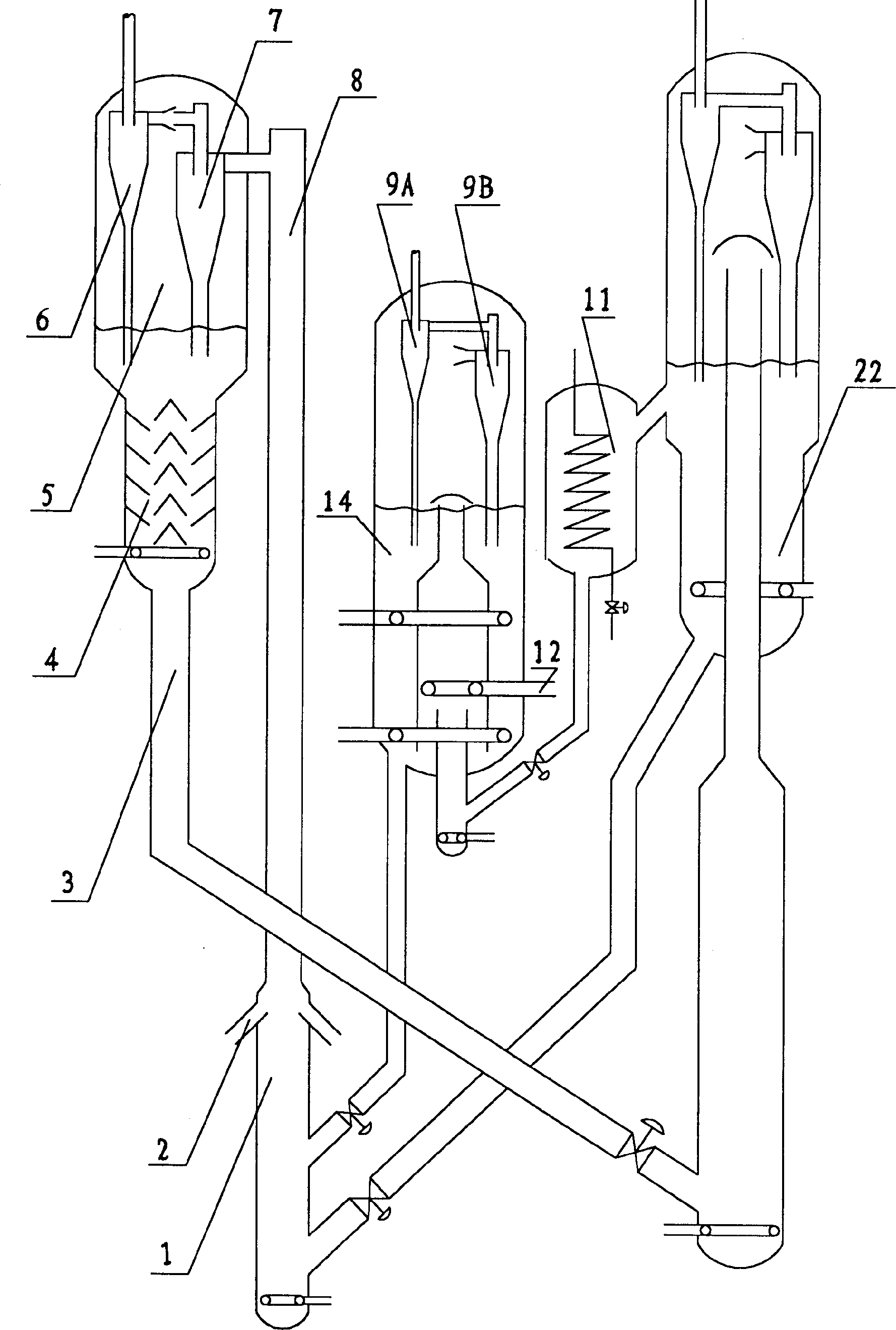
[0017] Implementation mode one: if figure 1 As shown, when adopting the inner and outer sleeve type circulating fluidized bed reactor 14 to implement the present invention, part of the regeneration agent enters the inside of the circulating fluidized bed reactor 14 inner sleeve (i.e. the reaction zone) after being cooled by the catalyst cooler 11 , contact and react with the gasoline raw material injected through the distributor 12, and the generated reaction oil gas is sent to the gasoline conversion product separation system after the entrained catalyst particles are removed by the cyclone separators 9A and 9B. The reacted catalyst enters the annular reaction space (that is, the stripping zone) between the inner and outer sleeves from the reaction zone, and the reaction oil gas carried by the catalyst is removed by stripping. Part of the stripped catalyst returns to the reaction zone to continue to participate in the reaction, while the rest of the catalyst is transported to...
Embodiment approach 2
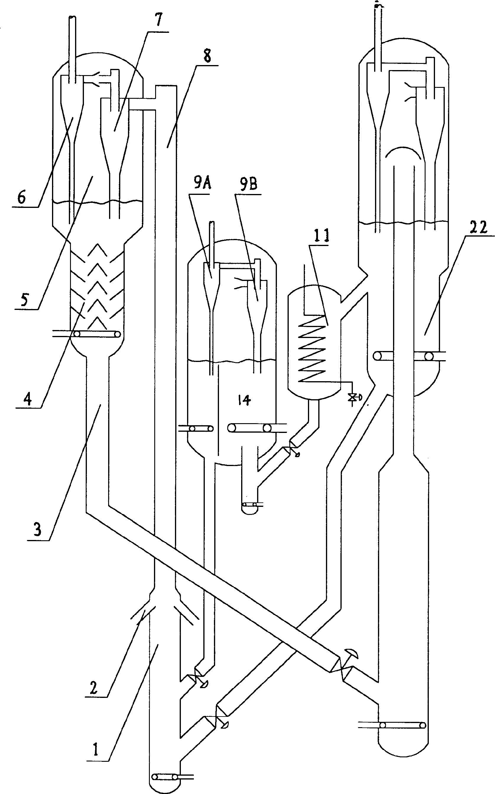
[0018] Implementation mode two: if figure 2 As shown, when the present invention is implemented in an internal clapboard type circulating fluidized bed reactor, part of the regeneration agent enters the reaction zone of the circulating fluidized bed reactor after being cooled by the catalyst cooler 11, and is mixed with the gasoline raw material injected through the distributor 12. After contacting and reacting, the generated reaction oil gas is sent to the gasoline conversion product separation system after the entrained catalyst particles are removed by cyclone separators 9A and 9B. The reacted catalyst enters the stripping zone from the reaction zone, and the reaction oil gas carried by the catalyst is removed by steam stripping. Part of the stripped catalyst returns to the reaction zone to continue to participate in the reaction, while the rest of the catalyst is transported to the pre-lift section 1 of the riser reactor 8, where it is mixed with the uncooled high-tempera...
Embodiment 1
[0021] This example illustrates: adopting the method provided by the present invention to carry out tests on a medium-scale riser reactor and an inner and outer sleeve type circulating fluidized bed reactor.
[0022] The principle flow of the device used in the test can be found in figure 1 . Such as figure 1 As shown, 40% by weight of the regenerated catalyst enters the reaction zone of the circulating fluidized bed reactor 14 after being cooled by the catalyst cooler 11, and contacts and reacts with the gasoline raw material injected through the distributor 12, and the generated reaction oil gas is passed through the cyclone Separators 9A and 9B remove the entrained catalyst particles and send them to the gasoline conversion product separation system. The reacted catalyst enters the stripping zone from the reaction zone, and the reaction oil gas carried by the catalyst is removed by steam stripping. 60% by weight of the stripped catalyst is returned to the reaction zone t...
PUM
| Property | Measurement | Unit |
|---|---|---|
| research octane number | aaaaa | aaaaa |
Abstract
Description
Claims
Application Information
 - R&D
- Intellectual Property
- Life Sciences
- Materials
- Tech Scout
- Unparalleled Data Quality
- Higher Quality Content
- 60% Fewer Hallucinations
Browse by: Latest US Patents, China's latest patents, Technical Efficacy Thesaurus, Application Domain, Technology Topic, Popular Technical Reports.
© 2025 PatSnap. All rights reserved.Legal|Privacy policy|Modern Slavery Act Transparency Statement|Sitemap|About US| Contact US: help@patsnap.com


