
Optical disk device and incline detection method

A technology of optical disc device and tilt detection, which is applied in the direction of using optical device, beam guiding device, recording/reproducing by optical method, etc., can solve the problems of inability to read fine signals correctly, temperature not reaching, and inability to record, etc., to achieve Effects of avoiding laser aging, suppressing cost increase, and improving recording quality

Inactive Publication Date: 2003-04-30
SANYO ELECTRIC CO LTD
View PDF0 Cites 9 Cited by
  • Summary
  • Abstract
  • Description
  • Claims
  • Application Information

AI Technical Summary

Problems solved by technology

If the beam spot diameter is increased, fine signals cannot be accurately read out
In the case of an optical disc that uses the heat of light to record, if the central intensity of light decreases, its temperature will not reach the specified value necessary for recording, so recording will not be possible; if the overall light intensity is increased to obtain a specified temperature, Then, the area reaching the specified temperature or higher will expand, so fine recording cannot be performed.

Method used


Image

  • Optical disk device and incline detection method
  • Optical disk device and incline detection method
  • Optical disk device and incline detection method

Examples


no. 2 Embodiment

[0149] Refer to the following Figure 25 ~ Figure 31 , to describe the second embodiment in detail, this is the case where only the disc tilt detection method described in the first embodiment is applied to the prior art 1.

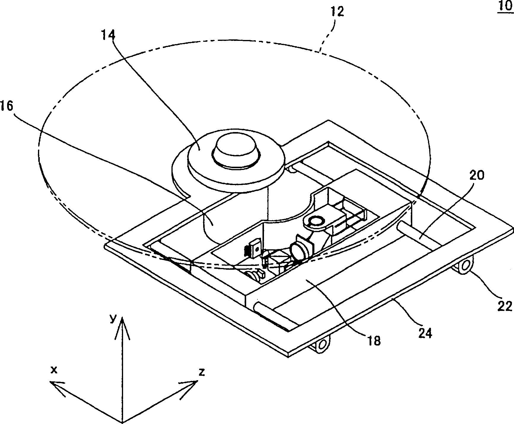
[0150] exist Figure 25 In the optical disc device 10 shown, the optical disc 12 as a signal recording and reproducing body is placed on the turntable 14, driven by the spindle motor 16 to rotate, and receives the light irradiation of the optical sensor 18, so as to record the signal on the optical disc 12, or from the optical disc 12 replay the signal. The optical sensor 18 is supported by a shaft 20 a and is movable in the axial direction of a shaft 20 supported by a shaft bracket 22 . The axle support 22 is secured to an axle support chassis 24 .

[0151] The spindle motor 16 is fixed to a spindle motor chassis 84 , and the spindle motor chassis 84 and the shaft holder chassis 24 are connected by a support shaft 86 . Also, a cam 88 for vertically o...


PUM


Abstract

An optical disc device and tilt detecting method are disclosed, wherein a light from laser diode 26 is switched into a parallel light by a collimator lens 34, and then reflected by a reflecting mirror 38 towards the direction of a field lens 40. The parallel light which passed a through hole 44 disposed on a field lens holder 42 is reflected by a disc, and the reflected light is incidented to a light sensor 60 through the collimator lens, a polarizing splitter 30, and prisms 52, 54. The parallel light which is reflected by the reflecting mirror is reflected by a mirror 50 integrally provided with the field lens holder, and is incidented to the light sensor 60 through the collimator lens, the polarizing splitter and prisms 52, 56. Any disc tilt and / or field lens tilt is thus detected from the output signal of a splitted light sensor of the light sensor 60. The effect of the invention is that a tilt servo is enabled at a small sized pickup device.

Description

technical field [0001] The present invention relates to an optical disc device and a tilt detection method, and more particularly to an optical disc device and a tilt detection method for detecting the tilt of an optical disc such as a DVD or a CD and reducing the influence of the disc tilt. Background technique [0002] As the recording capacity of the optical disc increases and its recording density increases, the beam spot irradiated on the optical disc has become very small for reproducing or recording signals. In particular, in an optical disc device for recording, in order to perform signal recording in a good state, the beam spot size is required to be smaller than that of an optical disc device for reproduction. In order to obtain a small beam spot, an objective lens with a large numerical aperture is used. As a result, the side effect is that the beam spot quality is significantly reduced due to the tilt of the optical disc. [0003] The so-called degradation of th...

Claims


Application Information

Patent Timeline
Patent Type & Authority Applications(China)
IPC IPC(8): G11B7/095G01B11/26G11B7/00G11B7/09G11B7/13G11B7/131G11B7/135G11B7/1356G11B7/1362G11B7/1374G11B7/1381G11B21/18
CPCG11B7/1356G11B7/1374G11B7/1381G11B7/1362G11B7/131G11B7/0956G11B2007/0006G11B7/09
Inventor 日比野清司
Owner SANYO ELECTRIC CO LTD
Learn More