
Draw-off chain-pulling bicycles

A bicycle and pulling type technology, which is applied to vehicle parts, vehicle gearboxes, transportation and packaging, etc., can solve the problems of difficulty in commercialization, increase structural complexity, etc., and achieve simple and compact structure, obvious labor-saving effect, and direction of force. correct effect

Inactive Publication Date: 2003-04-02
钱祖凡
View PDF1 Cites 7 Cited by
  • Summary
  • Abstract
  • Description
  • Claims
  • Application Information

AI Technical Summary

Problems solved by technology

Invisibly increases the complexity of the structure, making it difficult to achieve commercialization

Method used


Image

  • Draw-off chain-pulling bicycles
  • Draw-off chain-pulling bicycles
  • Draw-off chain-pulling bicycles

Examples


Embodiment Construction

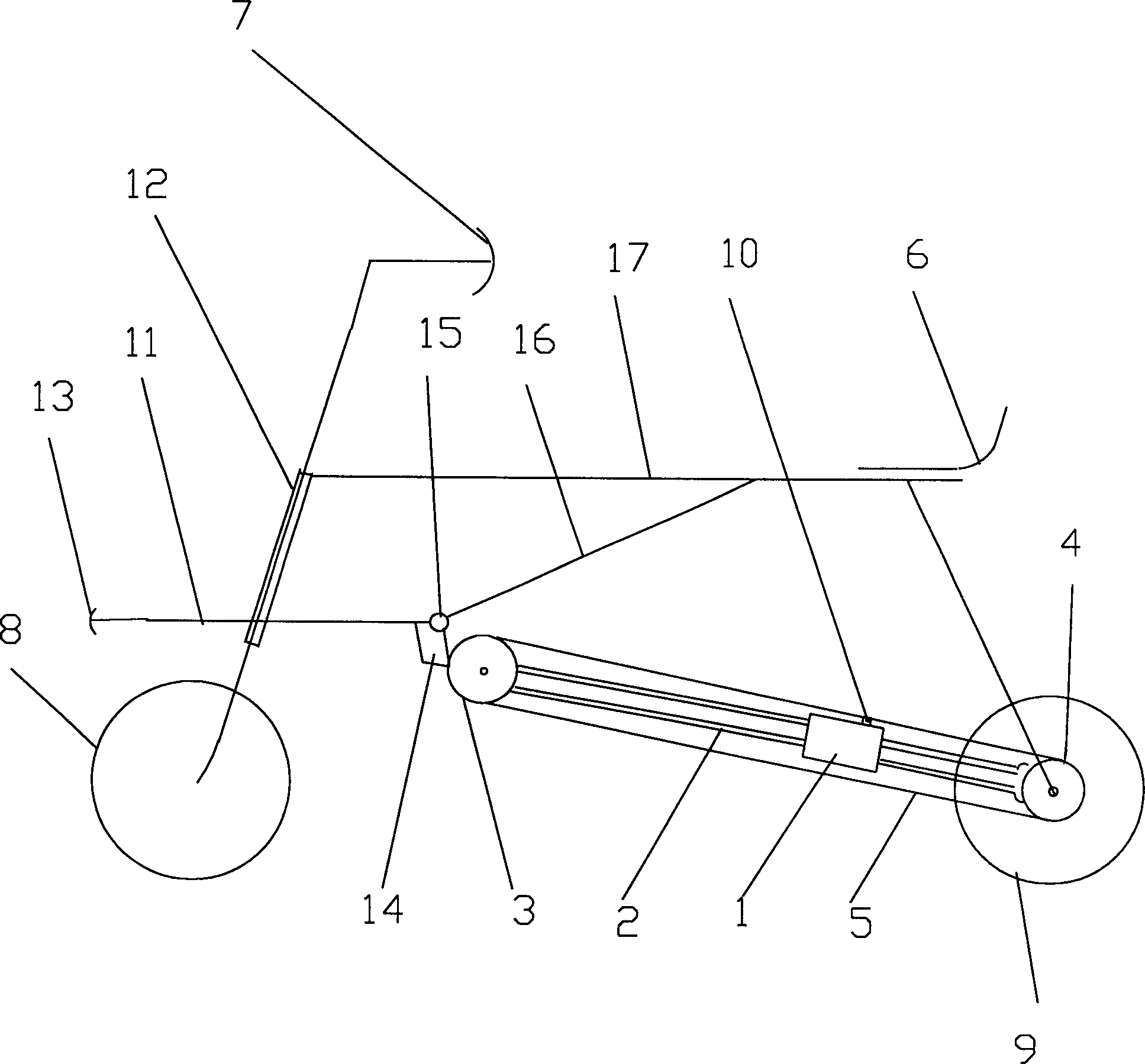
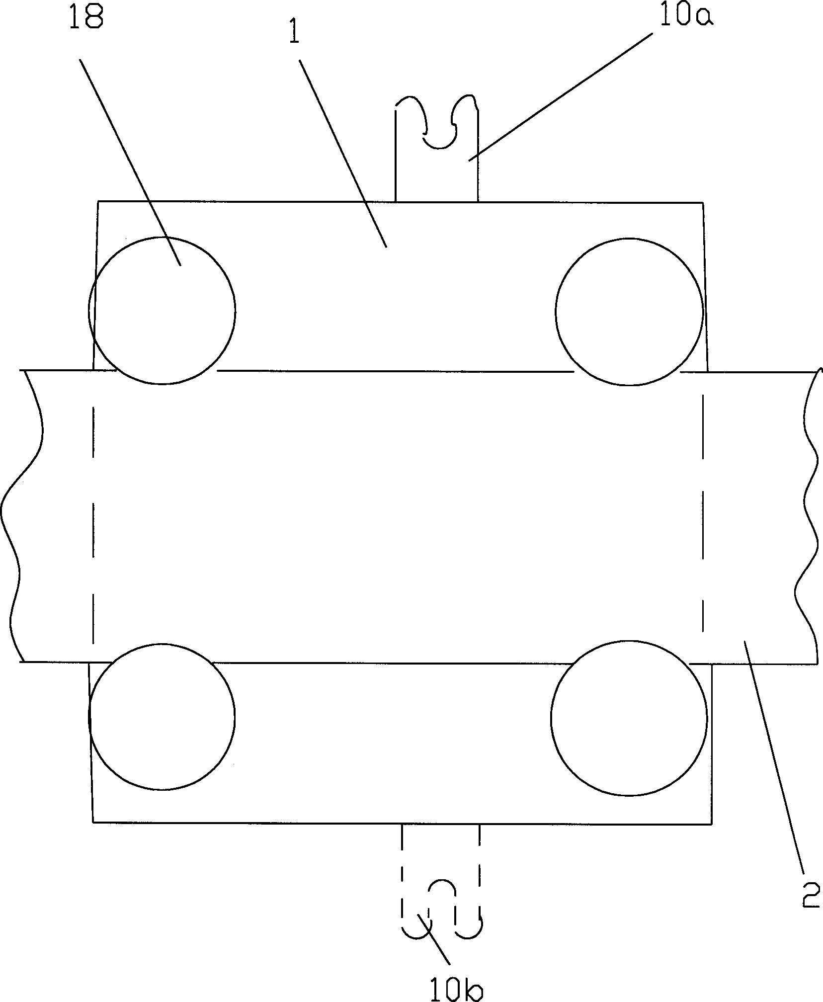
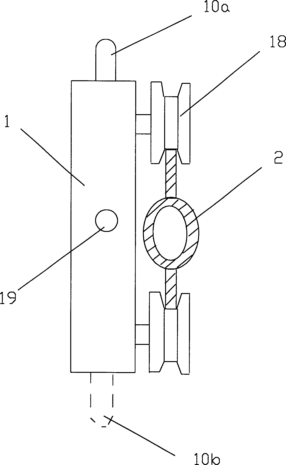
[0010] The structure of front wheel, rear wheel, steering shaft device, sprocket wheel, flywheel, beam, inclined beam and support frame of the present invention remains unchanged substantially, and tooth plate and pedal are canceled, and chain is lengthened. A driven sprocket (3) that can tighten the chain is arranged at the front end of the inclined beam (16). The derailleur (1) is installed on the right arm of the rear fork that acts as a guide rail. There are two, i.e. the upper catch chain tooth (10a) and the lower catch chain tooth (10b), the derailleur (1) is equipped with a power transmission lever (1b) that can eject the catch chain tooth. After the traction rope is connected through the rope hole (1a) on it, it turns to be connected to the left and right two foot covers (29) through the relevant pulley. In the present invention, the ratio of the moment arm to the heavy arm is exactly the ratio of the flywheel working radius to the wheel working radius, which can be se...


PUM


Abstract

A push-pull bicycle features structurally that its longer chain is stretched by a driven gear installed in the front end of oblique beam, and a chain driver with chain grasping jaw is installed to the right arm of back fork between upper and lower chain segments. When said chain driver is driven by a rope, its chain grasping jaw can grasp the chain and pull it forward, so drive bicycle forward. Its advantages are no need of big front gear and pedals, compact structure, and less pressing to perineum and scrotum of rider.

Description

Technical field: [0001] The invention relates to a bicycle using a linear force driving device. Background technique: [0002] Bicycles have a history of more than 100 years, and there are various improvements related to bicycles at present, such as improvements in the way of pedaling in circles, improvements in portability, and improvements in seat conditions. In particular, there are some patent applications every year for the improvement of how bicycles save effort. As the patent application of "LY-Z type bicycle" (application number 99108216.8) whose publication number is CN1275511A, the driving system is installed on the square inclined beam, and the pedal is exerted to drive the racks in the slideways on both sides of the inclined beam. The reset gear on the inclined beam controls, reciprocates, pulls the chain, and drives the bicycle. In this structural scheme, two movable racks are set in the slideway, and there are three flywheels on each side and the chains hangin...

Claims


Application Information

Patent Timeline
Patent Type & Authority Applications(China)
IPC IPC(8): B62M23/00
Inventor 钱祖凡
Owner 钱祖凡
Learn More