
Simulated electronic artificial hand

An electronic and palm technology, applied in the direction of prosthesis, medical science, artificial arm, etc., can solve the problems of great difference in shape, unsatisfactory use effect, etc., and achieve the effect of convenient holding

Inactive Publication Date: 2003-04-02
上海天竹康复科技发展有限公司
View PDF0 Cites 14 Cited by
  • Summary
  • Abstract
  • Description
  • Claims
  • Application Information

AI Technical Summary

Problems solved by technology

This kind of prosthetic hand is made of metal aluminum plate, and its shape is very different from the real hand. Even if you wear plastic gloves, the effect is still not ideal

Method used


Image

  • Simulated electronic artificial hand
  • Simulated electronic artificial hand
  • Simulated electronic artificial hand

Examples


Embodiment Construction

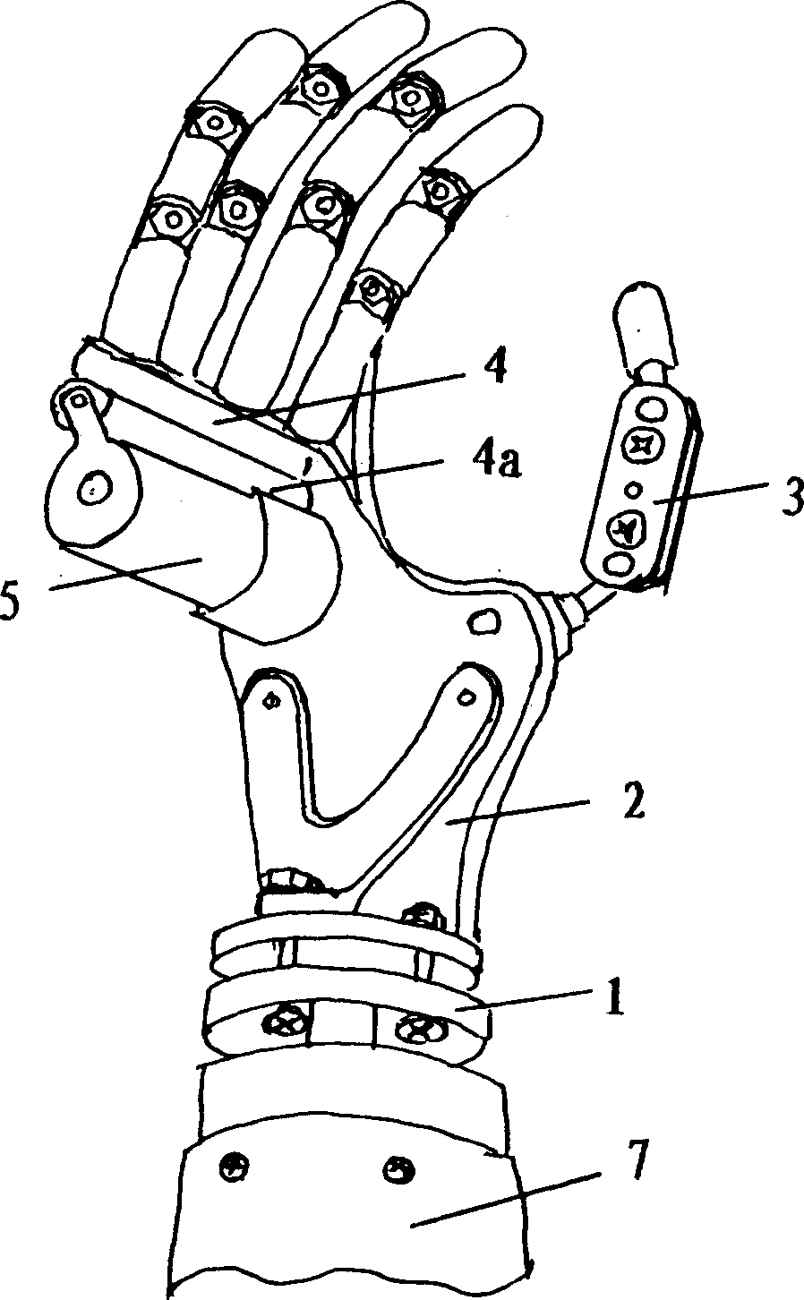
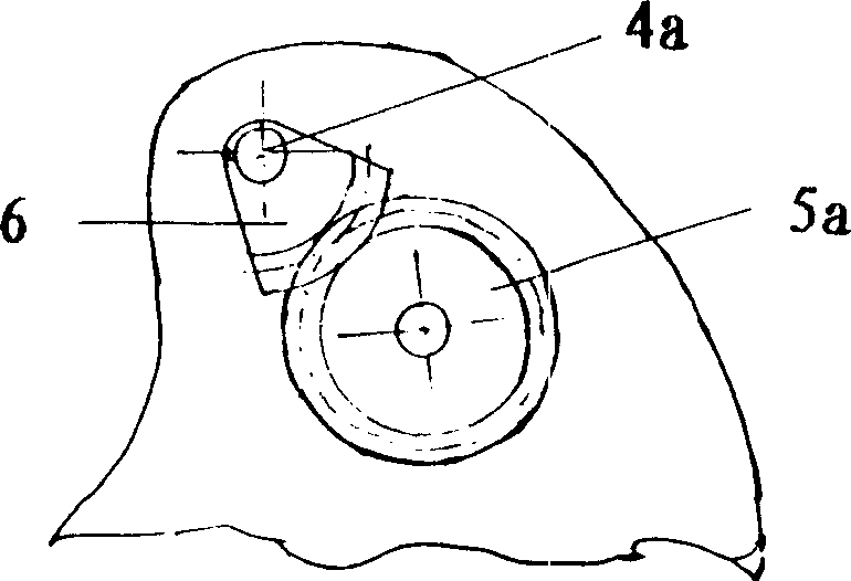
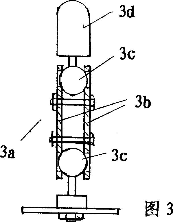
[0014] figure 1 It is a perspective view of an embodiment of the simulated electronic prosthetic hand of the present invention. As can be seen from the figure, this simulated electronic prosthetic hand includes a wrist joint 1, a palm seat 2 connected to the prosthetic wrist, a thumb 3, a finger frame 4, a DC motor 5, wherein the thumb 3 is fixed on the palm seat 2, and the finger frame 4 is located on one side of the finger frame shaft 4a, opposite to the thumb 3, and the DC motor 5 is fixed on the palm seat 2, and its deceleration The output shaft meshes with the sector gear 6 on the finger frame shaft 4a through a gear 5a. see figure 2 . Under the control of myoelectricity, the patient can make the motor 5 rotate forward or reverse according to his own wishes, so as to realize palm-to-palm movement, perform operations such as fetching and holding objects. The artificial hand is characterized in that it is structurally the same as the real hand, and has 14 joints in tota...


PUM


Abstract

A simulative artificial electronic hand is composed of wrist joint, palm seat linked to wrist joint, thumb, finger holder with 4 finger, miniature DC motor and 14 joints (two for thumb and three for each of fingers). Said wrist joint is a universal joint. The relative positions between joints and the angle of wrist joint can be regulated by another actual hand.

Description

[0001] Technical field: The present invention relates to a prosthetic body for rehabilitation, and specifically refers to an improvement of an electronic artificial prosthetic hand. Background technique: [0002] Due to many factors such as traffic accidents, natural disasters, industrial injuries, wars and congenital diseases, there are many patients with disabled limbs. According to statistics, there are tens of millions of patients with residual limbs all over the world. In order to allow people with disabled limbs to take care of themselves and improve their quality of life as much as possible, various prosthetic hands have emerged in recent years. Electronic prosthetic hands are welcomed by people with disabled limbs because they rely on external energy supply and cooperate with bioelectric control to realize control according to people's wishes. [0003] The current electronic prosthetic hand simplifies the four fingers into two pieces, which are opposite to one piece o...

Claims


Application Information

Patent Timeline
IPC IPC(8): A61F2/54A61F2/56
Inventor 胡天培斯扬
Owner 上海天竹康复科技发展有限公司
Learn More