Butterfly valve
A butterfly valve and valve body technology, applied in the field of butterfly valves, can solve the problems of seat ring deterioration, failure to achieve sealing, large useless torque, etc.
- Summary
- Abstract
- Description
- Claims
- Application Information
AI Technical Summary
Problems solved by technology
Method used
Image
Examples
Embodiment Construction
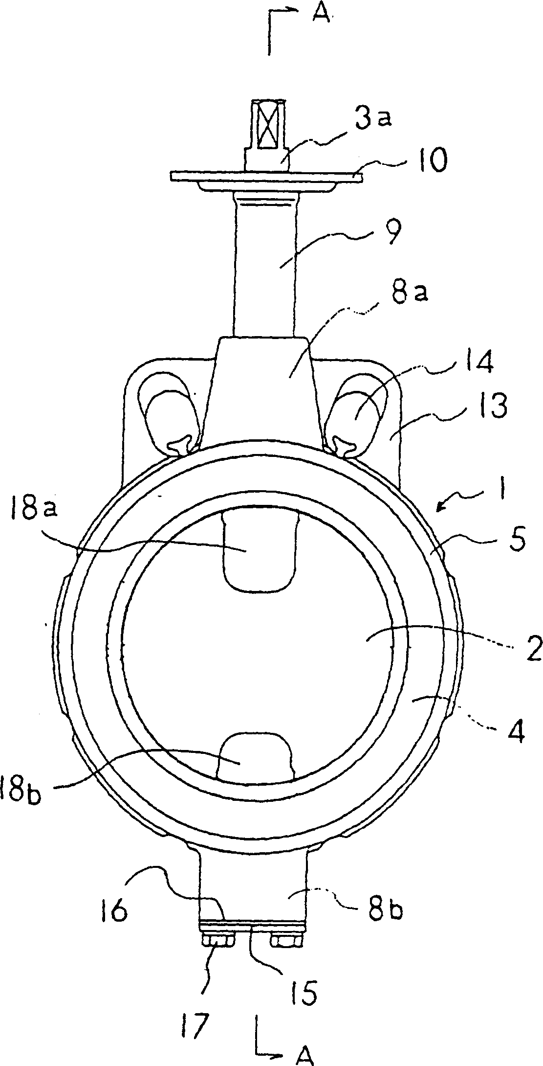
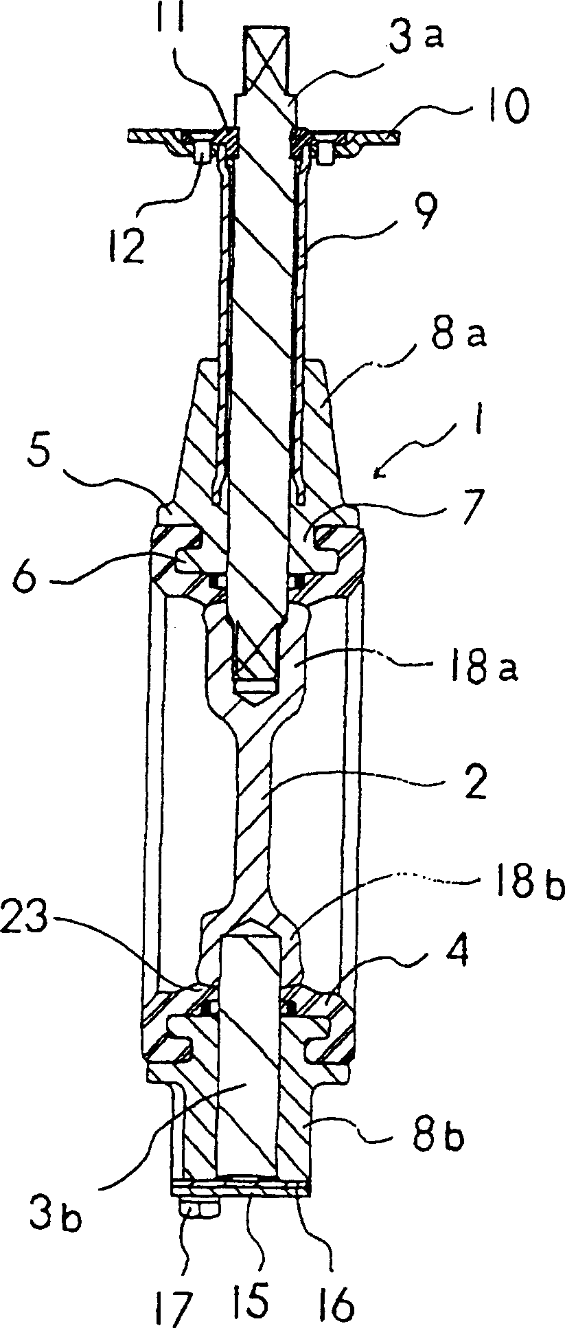
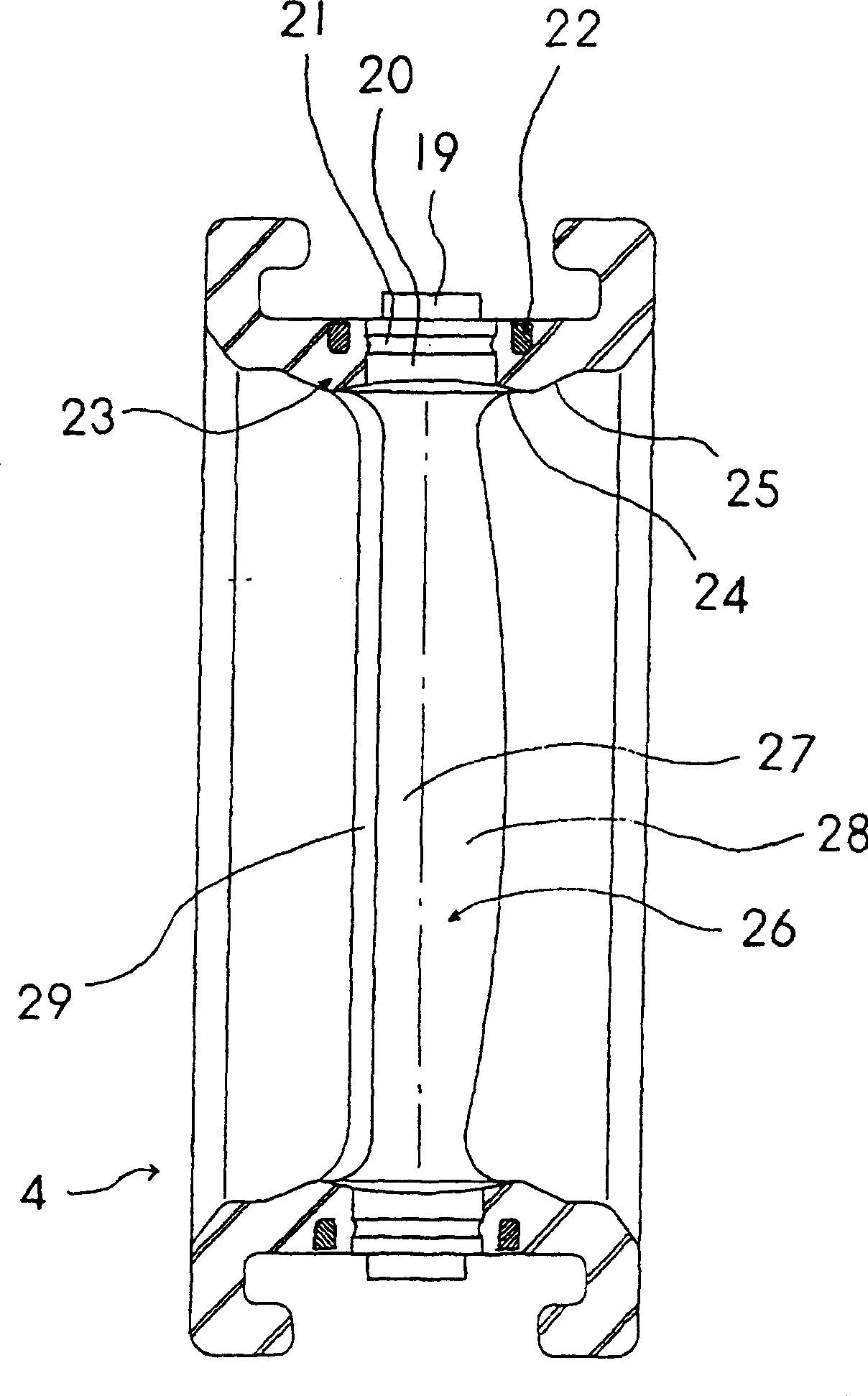
[0028] The embodiment of the butterfly valve of the present invention will be described below with the accompanying drawings. figure 1 It is the front view of the butterfly valve of the present invention, figure 2 for along figure 1 The A-A line sectional view, image 3 is a sectional view of the seat ring along the direction of the valve axis, Figure 4 It is a sectional view of the seat ring along the direction perpendicular to the valve axis.
[0029] The butterfly valve is set at the connecting part of the pipe that can flow in it, and performs on-off control and flow adjustment of the flow path. It has: an annular valve box 1, which is clamped by two pipes along its axial direction (flow path direction); A substantially disc-shaped valve body 2 installed inside the valve box 1; the valve body 2 is freely rotatably supported around the valve shaft 3 (the axis passing through the center of the valve box 1 in a direction perpendicular to the direction of the flow path)...
PUM
 Abstract
Description
Claims
Application Information
 - R&D
- Intellectual Property
- Life Sciences
- Materials
- Tech Scout
- Unparalleled Data Quality
- Higher Quality Content
- 60% Fewer Hallucinations
Browse by: Latest US Patents, China's latest patents, Technical Efficacy Thesaurus, Application Domain, Technology Topic, Popular Technical Reports.
© 2025 PatSnap. All rights reserved.Legal|Privacy policy|Modern Slavery Act Transparency Statement|Sitemap|About US| Contact US: help@patsnap.com


