Switch

A switch and electrical switch technology, applied in the field of switches, can solve the problems of not being able to install ribs, lengthen the effective electrical distance, etc., and achieve the effect of extending the leakage distance

Inactive Publication Date: 2002-12-04
ABB PATENT GMBH
View PDF0 Cites 2 Cited by
  • Summary
  • Abstract
  • Description
  • Claims
  • Application Information

AI Technical Summary

Problems solved by technology

Contrary to the outer wall, it cannot be provided with ribs, surrounding battens or similar structures, since these would increase the electrical effective distance

Method used


Image

  • Switch
  • Switch
  • Switch

Examples


Embodiment Construction

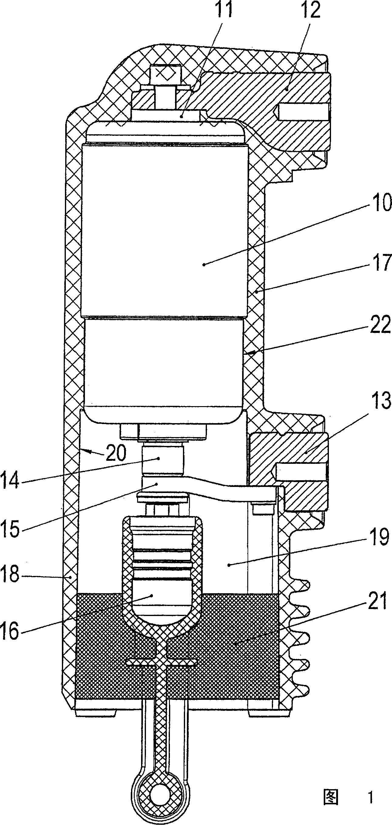
[0017] FIG. 1 shows a vacuum chamber 10 with a current input 12 at its upper end 11 and a current output 13 at its lower end. Protruding from the vacuum chamber 10 is a contact rod 14 to which one end of a conductive strip 15 is connected, while the other end thereof is electrically conductively fastened to the current output element. Connected to the displaceable contact rod 14 is a transmission element 16 which is coupled to a transmission not shown in detail.

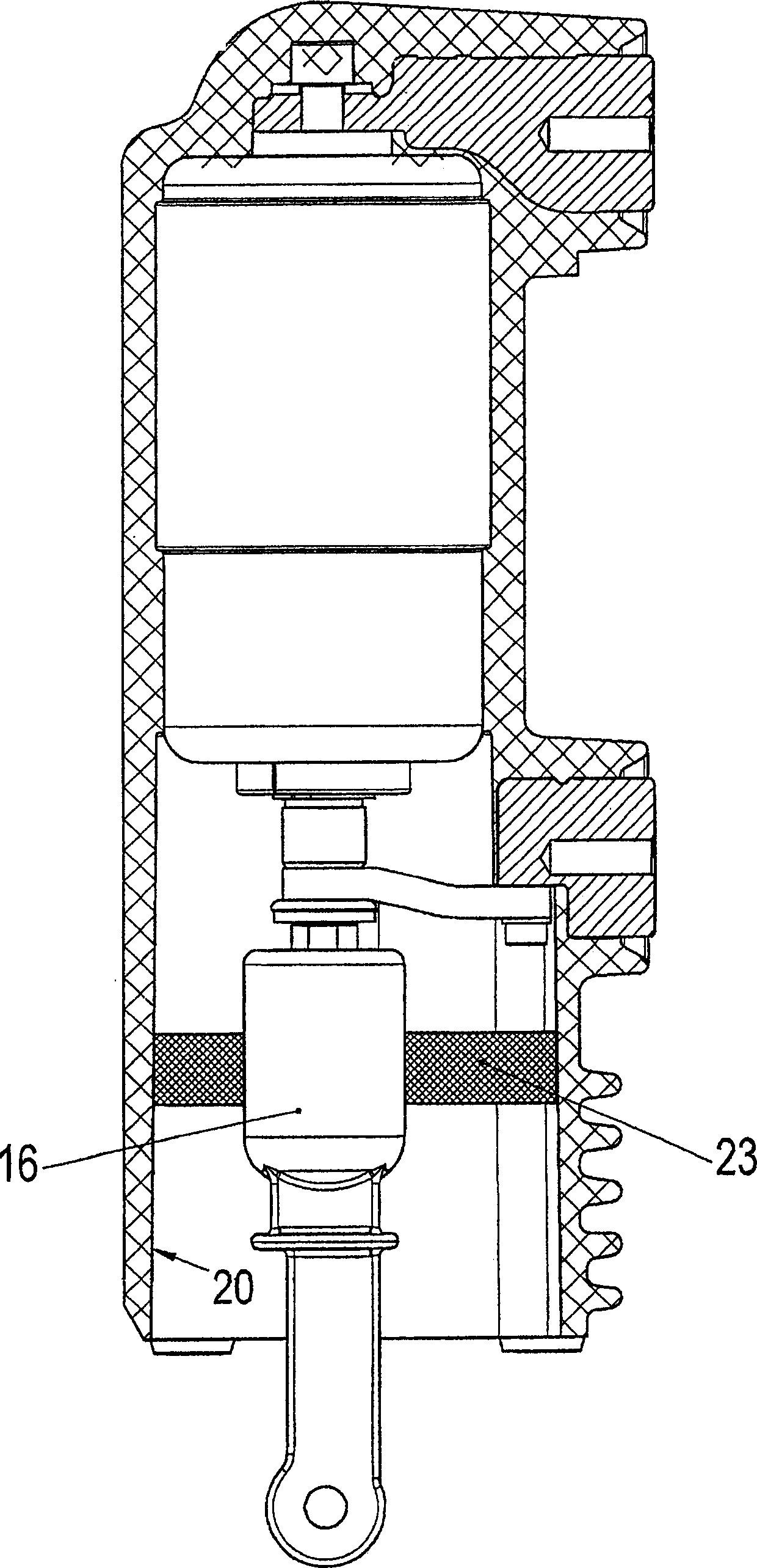
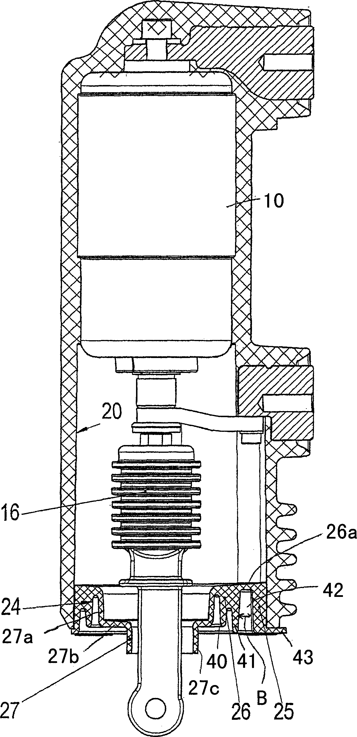
[0018] The vacuum chamber 10 together with the current input and output parts 12 and 13 is injected in a casting resin 17, wherein at the lower end of the vacuum chamber is connected a cylindrical tube 18 which encloses a free cavity 19 or access cavity 19. Via this access chamber 19 the transmission element 16 extends as far as the movable contact rod 14 .

[0019] The inner surface 20 of the cylindrical tube 18 is smooth, and in order to avoid dielectric discharges along this inner surface, the inner cavity 19 is...


PUM


Abstract

The invention describes an electrical switch inserted in an insulating material, such as cast resin or ceramics, whose movable contacts pass through a tubular insulating member open at one end and are connected to the transmission via a transmission element, wherein in free space A sealing element is provided in the cavity, and the sealing element is at least pressed or firmly pasted on the inner surface of the insulating member, so as to avoid dielectric discharge from high voltage potential to ground potential through the inner surface.

Description

technical field [0001] The invention relates to a switch according to the preamble of claim 1 . technical background [0002] Such a switch can be inserted as an outdoor switch in a ceramic tube, wherein the transmission element for the moving contact is guided downwards through a free space to a transmission. Such a switch can also be a vacuum chamber in a similar manner, which has current input and output parts arranged perpendicular to the central axis; a transmission element is arranged for the action of the movable contact part, which is arranged in the longitudinal direction of the central axis direction. If such a vacuum chamber is injected into the casting resin, free space is likewise provided in the area of ​​the transmission element in order to enable the transmission element to be guided to the movable contact piece. [0003] In order to be able to remove the core easily, the free space or the inner surface of the access cavity is designed...

Claims


Application Information

Patent Timeline
Patent Type & Authority Applications(China)
IPC IPC(8): H01H33/662
CPCH01H33/66207H01H2033/66223H01H2033/6623
Inventor E·杜尔尼H·J·克莱斯H·贝格
Owner ABB PATENT GMBH
Why Eureka
Try Eureka