Multipoint plug for electrically connecting metal strip conductors arranged on both sides of a circuit board

A printed circuit board, electrical contact connection technology, applied in the direction of circuits, contact parts, conductive connections, etc., can solve problems such as large space positions

Inactive Publication Date: 2009-04-08
SIEMENS AG
View PDF11 Cites 0 Cited by
  • Summary
  • Abstract
  • Description
  • Claims
  • Application Information

AI Technical Summary

Problems solved by technology

This design requires a relatively large space especially due to the large distance between adjacent contact elements

Method used


Image

  • Multipoint plug for electrically connecting metal strip conductors arranged on both sides of a circuit board
  • Multipoint plug for electrically connecting metal strip conductors arranged on both sides of a circuit board
  • Multipoint plug for electrically connecting metal strip conductors arranged on both sides of a circuit board

Examples


Embodiment Construction

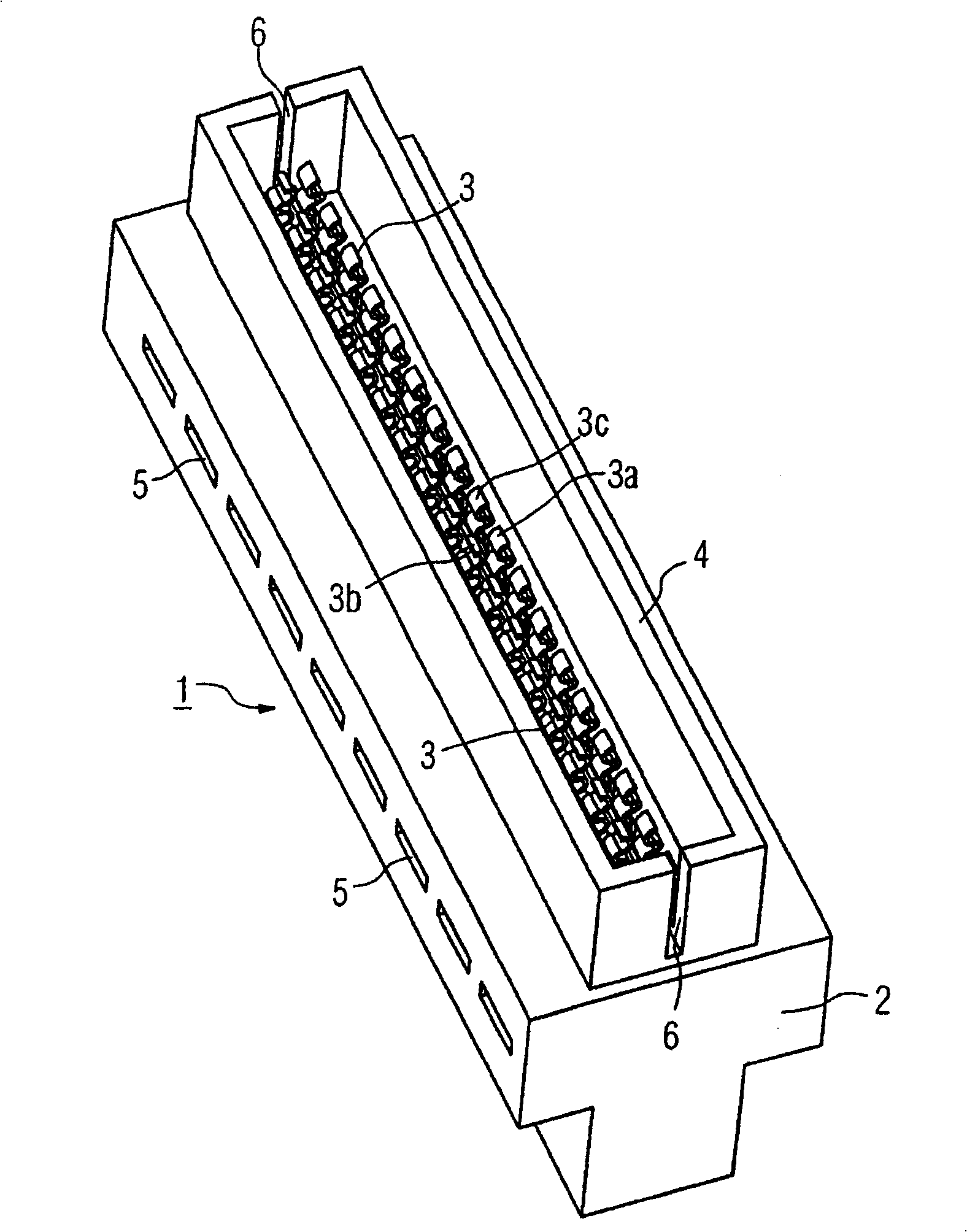
[0019] figure 1 A contact plate 1 with a base body 2 is shown. Two rows of oppositely positioned elastic contact elements 3 , 3 a , 3 b , 3 c are arranged on the base body 2 along its longitudinal direction. These contact elements are made of electrically conductive material and are designed to be elastic in opposite directions. In each case two mutually opposite contact elements (for example 3 a and 3 b ) are electrically isolated from each other. The spring elements 3 , 3 a , 3 b , 3 c are surrounded by a box-shaped enclosure 4 , thereby preventing mechanical damage to the contact elements, for example during storage, transport and careless handling of the contact plate. Inside the base body 2 there are electrical leads (in figure 1 not shown in ), these electrical leads connect each contact element 3, 3a, 3b, 3c to a connection on the outside of the base body.

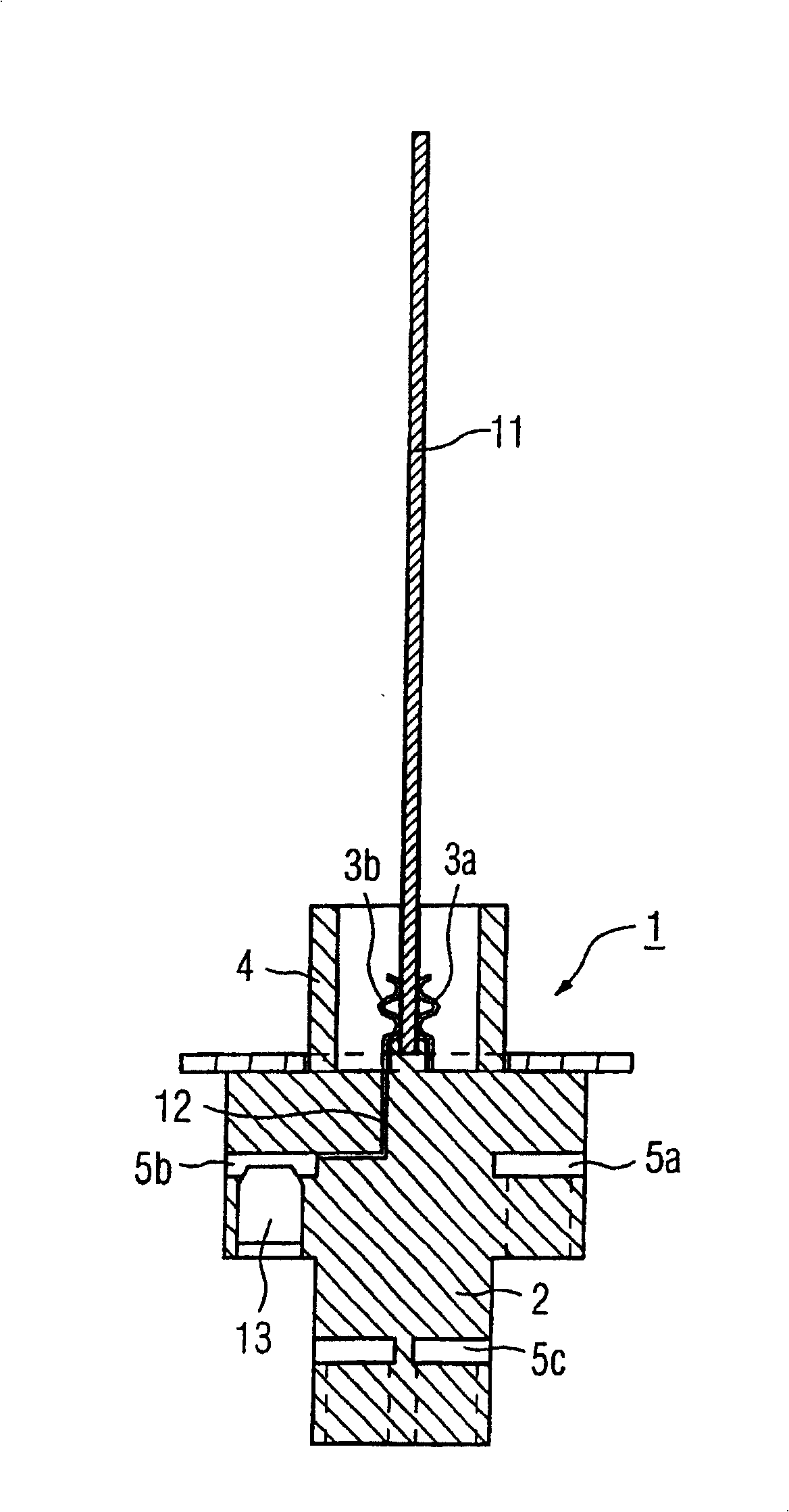
[0020] For contacting conductor tracks arranged on a printed circuit board, the printed circuit board is inse...


PUM


Abstract

The invention relates to a multipoint plug (1) for electrically connecting metallic strip conductors (21, 22) arranged on both sides of a circuit board (11) comprising a base body (2) provided with mutually opposite flexible contacts (3, 3a, 3b, 3c) which are longitudinally arranged in such a way that the front face of the circuit board (11) is insertable between said contacts (3, 3a, 3b, 3c), thereby producing electric contact thereof with the strip conductors (21, 22). The opposite contacts (3, 3a, 3b, 3c) are electrically insulated with respect to each other inside the base body (2). The aim of the invention is to develop a small-sized multipoint plug which exhibits as high electric strength as possible. For this purpose, a recess (24) is shaped between opposite contacts (3, 3a, 3b, 3c) in a longitudinal direction of the base body. When the circuit board (11) is inserted, said recess encompasses the frontal face thereof in such a way that an extended creepage distance is formed between opposite contacts (for instance, 3a, 3b).

Description

technical field [0001] The invention relates to a contact board for electrically contacting metal conductor tracks extending on both sides of a printed circuit board, wherein the contact board has a base body with a plurality of such Resilient contact elements opposite each other, ie such that the printed circuit board can be inserted with its one end side or narrow side between contact elements opposite each other, for contacting the conductor tracks on the printed circuit board with the The elements are electrically contacted, wherein the individual mutually opposite contact elements are electrically isolated from one another within the main body. Background technique [0002] Such a contact plate is commonly known, for example, as a so-called PCI plug connector, which is mounted, for example, on a main board (motherboard) of a computer. Since the so-called PCI plug connector is only used for low currents and voltages, the individual contact elements of the PCI plug conne...

Claims


Application Information

Patent Timeline
IPC IPC(8): H01R12/18H01R13/11H01R13/703
CPCH01R12/515H01R23/7068H01R13/7034H01R12/721H01R9/093
Inventor 埃里克·卢德托马斯·舒普勒
Owner SIEMENS AG
Why Eureka
Try Eureka