
Golf club head and its surface treatment method

A technology for golf club heads, metal surfaces, applied to golf balls, golf clubs, rackets, etc.

Inactive Publication Date: 2002-10-09
MIZUNO CORPORATION
View PDF0 Cites 0 Cited by
  • Summary
  • Abstract
  • Description
  • Claims
  • Application Information

AI Technical Summary

Problems solved by technology

Perform wet barrel grinding on the club head body for a certain period of time and then perform dry barrel grinding for a certain period of time

Method used


Image

  • Golf club head and its surface treatment method
  • Golf club head and its surface treatment method
  • Golf club head and its surface treatment method

Examples


Embodiment Construction

[0057] The preferred embodiment of the present invention will be described below with reference to the accompanying drawings.

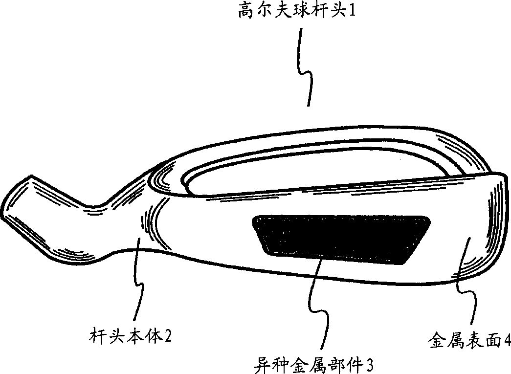
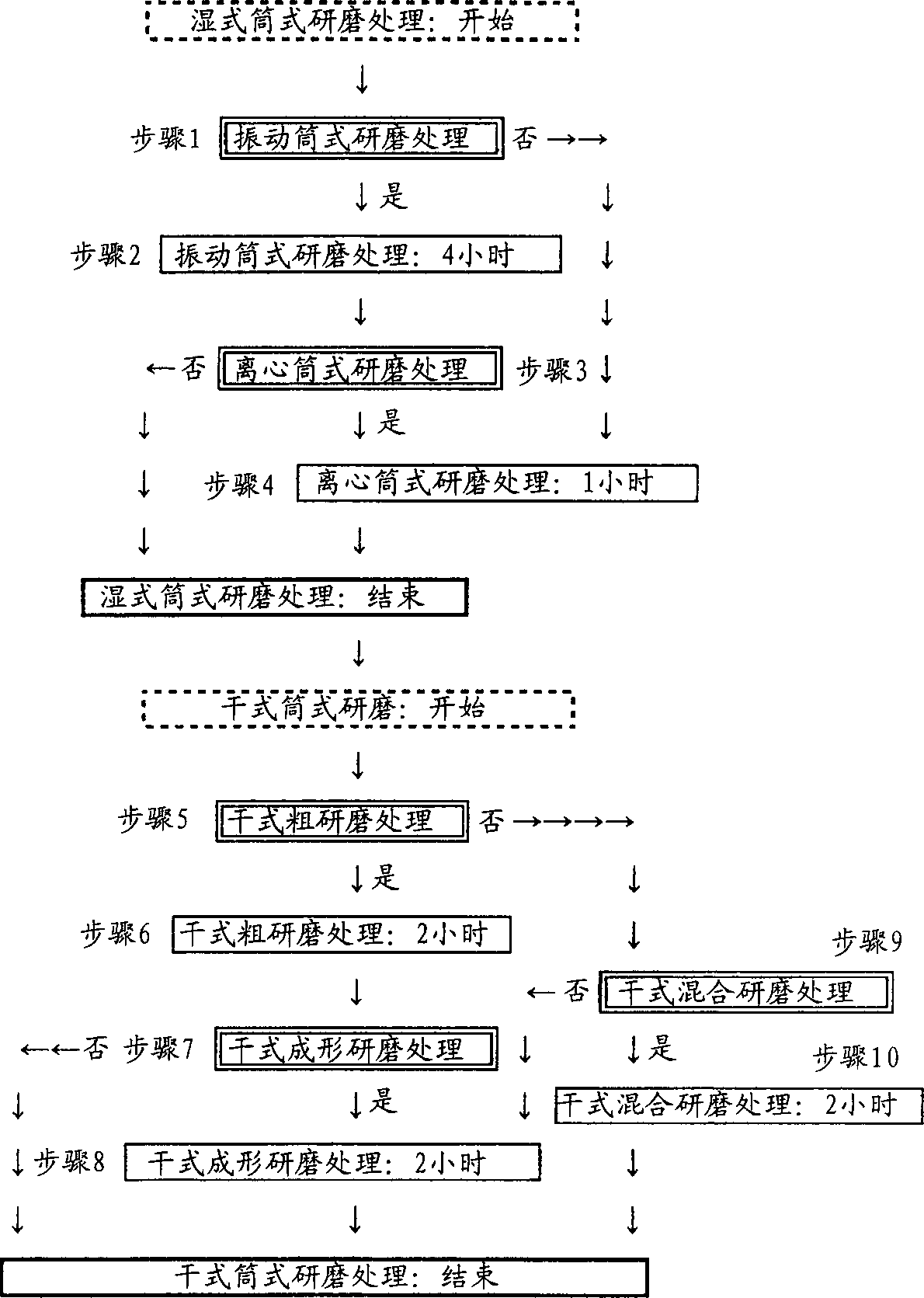
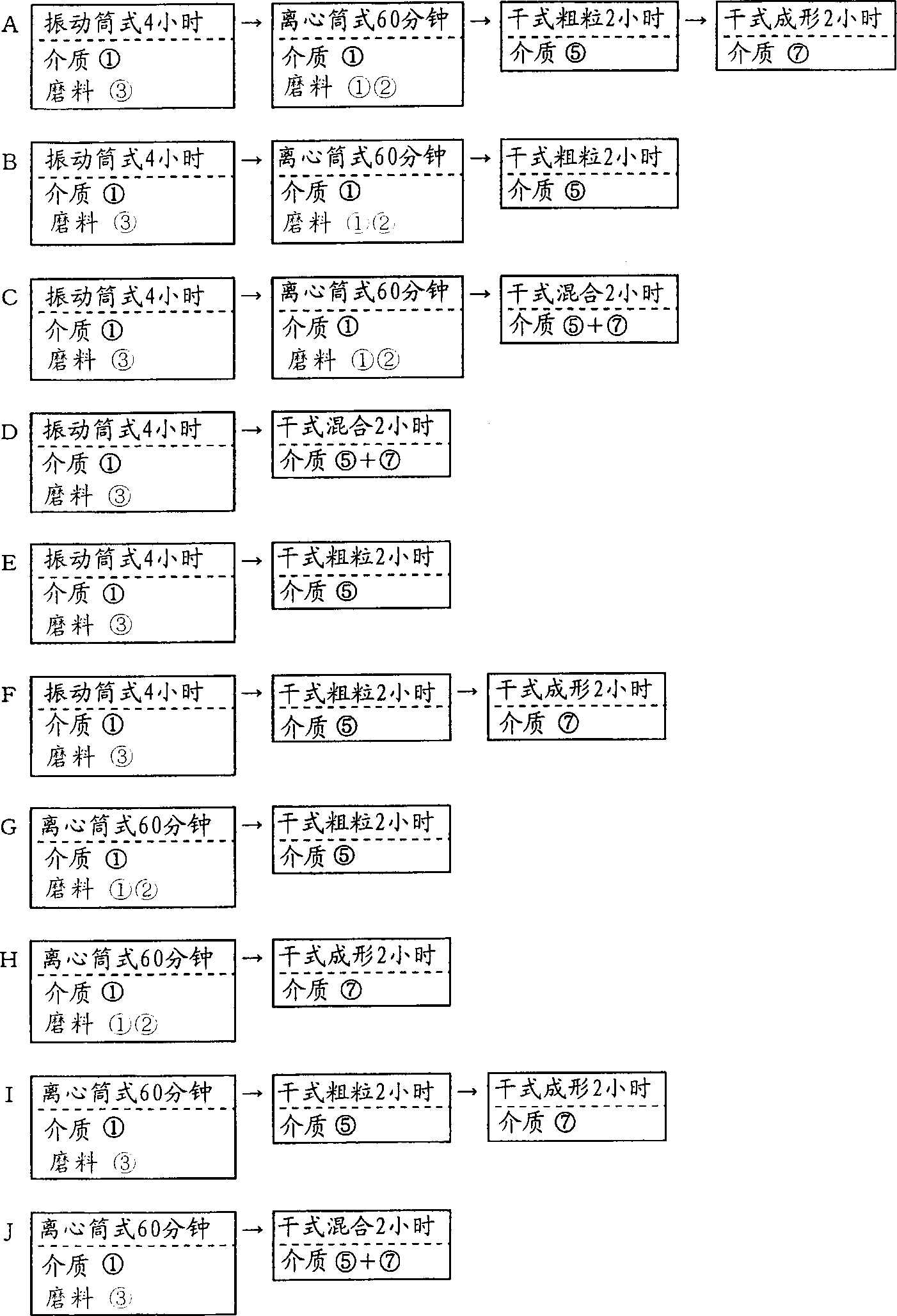
[0058] figure 1 It is a view of forming the golf club head 1 of this embodiment into an iron club head. The golf club head 1 of this embodiment is constituted by embedding a dissimilar metal member 3 formed of tungsten steel in a portion corresponding to a "sole" of a club head body 2 formed of stainless steel. The present invention implements base surface grinding treatment on the golf club head 1, and then image 3 Each grinding method shown is generally implemented by "wet cylinder grinding process" and "dry cylinder grinding process".

[0059] First, the formation of the golf club head 1 and the "surface treatment" performed on the golf club head 1 will be described.

[0060] The golf club head 1 of this embodiment is composed of the head body 2 and the different metal member 3 as described above. The aforementioned club head body 2 is formed...


PUM


Abstract

The golf club head of the present invention performs surface treatment and shaping by subjecting its metal surface to multiple barrel grinding treatments. Therefore, it can be formed into a state in which the luster of each metal surface of the club head body and dissimilar metal parts has subtle differences. , it is possible to create a creation that clearly distinguishes the state of the club head body and dissimilar metal parts. Therefore, it is possible to easily and reliably provide a golf club head of excellent quality that has not been available in the past.

Description

technical field [0001] The present invention relates to a metal golf club head subjected to grinding treatment and a surface treatment method of the golf club head, in particular to a golf club head with wet grinding treatment and dry grinding treatment on the surface and its surface treatment method. surface treatment method. Background technique [0002] For the method of surface treatment of metal golf club heads represented by iron club heads, "electroplating treatment", "painting treatment", "texture treatment of the surface of the production material", etc. have been known in the past, and the method of "production of Texture treatment of the surface of the material (hereinafter referred to as texture treatment)" to carry out the aforementioned surface treatment is very common. [0003] This "texture treatment" generally consists of "rough grinding treatment" and "shaping grinding treatment". The above-mentioned "rough grinding treatment" is ...

Claims


Application Information

Patent Timeline
IPC IPC(8): A63B53/04A63B102/32
Inventor 川岛正広
Owner MIZUNO CORPORATION
Learn More