Single sheet paper transferring roller

A transfer roller, sheet-fed technology, used in the direction of shipping and packaging, printing, printing presses, etc.

Inactive Publication Date: 2002-08-28
HEIDELBERGER DRUCKMASCHINEN AG
View PDF0 Cites 7 Cited by
  • Summary
  • Abstract
  • Description
  • Claims
  • Application Information

AI Technical Summary

Problems solved by technology

[0002] In the known sheet-fed transport cylinders of this type there is the problem that, depending on how much the second comb segment is rotated relative to the first comb segment, a larger or s...

Method used


Image

  • Single sheet paper transferring roller
  • Single sheet paper transferring roller
  • Single sheet paper transferring roller

Examples


Embodiment Construction

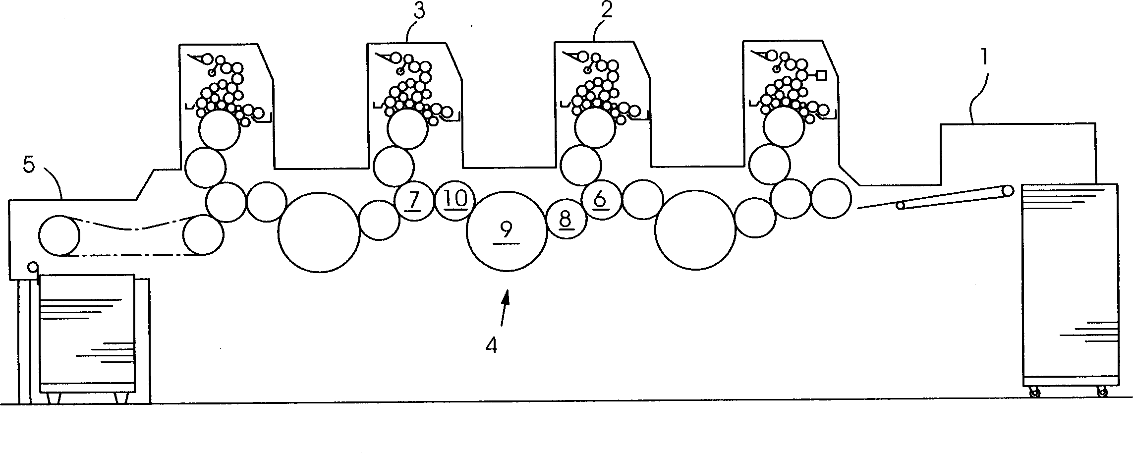
[0012] exist figure 1 shows a tandem sheet-fed rotary printing press with a sheet feeder 1, with printing units 2, 3 for printing sheet-fed substrates according to the offset printing method, with a printing unit 2, 3 3 between an overturning device 4 and a sheet-fed delivery device 5 .

[0013] Each printing unit 2 , 3 comprises an impression cylinder, a blanket cylinder and an opposing impression cylinder 6 , 7 . The turning device 4 has three sheet-sheet transport cylinders 8 , 9 , 10 arranged between opposing impression cylinders 6 , 7 . The sheet-fed transfer cylinder 9 acts as a so-called storage cylinder and holds the sheet-fed printing material firmly on its leading edge by means of its gripper system. The sheet-fed transfer cylinder 10 acts as a so-called reversing cylinder (Wendetrommel) and by means of its gripper system grabs a rear edge of the sheet-fed substrate in order to turn it over and remove it from the sheet-fed transfer drum. 9 up and down.

[0014] A...


PUM


Abstract

The invention relates to a sheet-fed transmission cylinder (9) in a sheet-fed printing device, comprising a first comb-shaped section (11) and a second comb-shaped section (12), the second comb-shaped section (12) Supported rotatably relative to the first comb section (11), so that it can be adjusted to a length corresponding to the specification of the sheet-fed substrate, the sheet-fed transport cylinder (9) of the present invention is characterized in that the comb-shaped The interspaces (15) between the comb teeth (14) of the segments (11, 12) are covered by means of at least one cover part (19).

Description

technical field [0001] The invention relates to a sheet-fed transport cylinder of the type specified in the preamble of claim 1 in a sheet-fed printing machine, the sheet-fed transport cylinder comprising a first comb-like segment and a second comb-like segment, the The second comb section is mounted rotatably relative to the first comb section for adjustment to a format length corresponding to the sheet-fed printing material. Background technique [0002] In the known sheet-fed transport cylinders of this type there is the problem that, depending on how much the second comb segment is rotated relative to the first comb segment, a larger or smaller gap is produced between the teeth of the comb segment. Interstices through which air flows from the inside to the outside of the sheet-fed transfer cylinder under the action of centrifugal force. Undesirable air escape from the sheet transfer rollers can cause uncontrolled sheet-fed substrates to cover these gaps during transfer ...

Claims


Application Information

Patent Timeline
IPC IPC(8): B41F21/10B65H5/12
CPCB41F21/106
Inventor 克里斯蒂安·希贝
Owner HEIDELBERGER DRUCKMASCHINEN AG
Why Eureka
Try Eureka