
Vision corrector

A vision correction and optometry technology, applied in the field of vision correction instruments, can solve the problems of adjusting qi and blood, failing to fully correct the eyes, and taking a long time to correct, achieving the effect of large eye activity and stimulating the development of visual cells

Inactive Publication Date: 2002-08-14
郭占敏
View PDF0 Cites 11 Cited by
  • Summary
  • Abstract
  • Description
  • Claims
  • Application Information

AI Technical Summary

Problems solved by technology

Using this kind of therapeutic apparatus, due to the small field of vision, the eyes can only move in a small range, the amount of eye activity is small, the correction time is long, and the recovery of vision is only effective in a short period of time, and it is easy to rebound after a long time; this therapeutic apparatus cannot make the eyes The full exercise of each organ cannot comprehensively exercise and coordinate the various organs of the eye, and cannot improve the nutritional supply of the eye and adjust the qi and blood from the source, so it is impossible to fully correct visual impairments such as amblyopia, strabismus, hyperopia, and myopia

Method used


Image

  • Vision corrector
  • Vision corrector
  • Vision corrector

Examples


Embodiment Construction

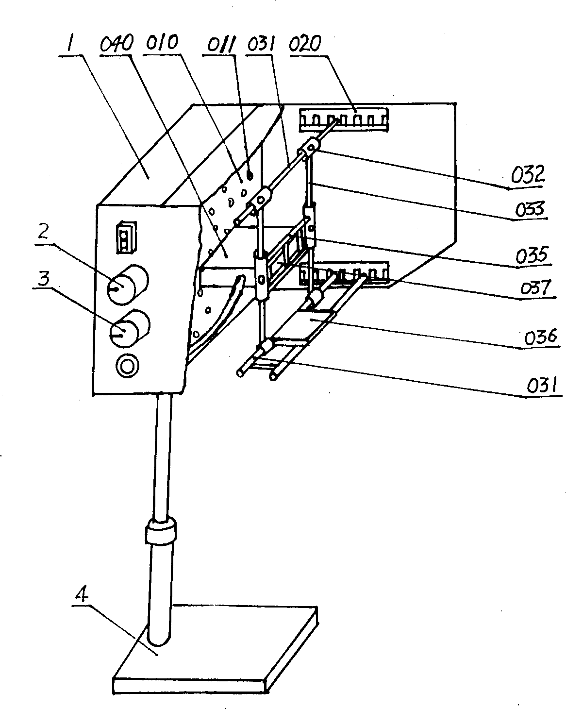
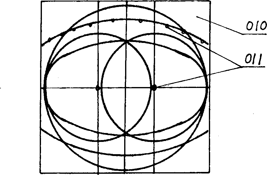
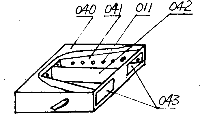
[0032] like figure 1 , figure 2 As shown, the present invention comprises the main visual target plate 010 in the casing 1 and the casing 1, the main visual target plate 010 is provided with several visual targets 011 within the maximum field of view of the relative people’s eyes, and the maximum visual field is: the eyes are kept to When the distance of the main visual target plate 010 is constant, the largest area that can be seen when the eyeball rotates up, down, left, and right; the visual target 011 of the vision corrector of the present invention changes regularly under the control of the controller, and different positions can be selected according to needs The visual mark 011 flashes, the controller is connected with the speed control knob 2 and the programming knob 3, the controller 8 can be controlled by mechanical control or programming circuit, the programming control circuit is mainly composed of an oscillating circuit and a control circuit, and the output frequ...


PUM


Abstract

A vision unscrambler for treating amblyopia, myopia, hyperopia and strabismus is composed of case body, main visual target board in the case body, and controller for controlling the flash variation of visual targets. A number of visual targets are arranged in the maximal visnal filed on said main visual target boards. The flash variation of visual targets forces eyes to move in the maximal visualfield, so exercising and coordinating the functions of eyes and promoting benigh development of eyes. Its advantage is short unscrambling period.

Description

Technical field: [0001] The invention relates to a vision correction instrument. Background technique: [0002] At present, the arrangement of the visual targets of the eye care therapeutic instrument is within a small field of view. For example, if the visual targets are arranged in a lens barrel, the visual targets are arranged in a triangle, straight line, or small arc, and usually consist of three or four visual target light-emitting diodes. A group of visual targets, each group of visual targets flashes alternately or simultaneously, and then forms a kaleidoscopic image through the refraction and reflection of the three mirrors. Using this kind of therapeutic apparatus, due to the small field of vision, the eyes can only move in a small range, the amount of eye activity is small, the correction time is long, and the recovery of vision is only effective in a short period of time, and it is easy to rebound after a long time; this therapeutic apparatus cannot make the eyes...

Claims


Application Information

Patent Timeline
IPC IPC(8): A61H5/00
Inventor 郭占敏
Owner 郭占敏
Learn More