
Fixing roll assembly of electronic photography image-forming device

A technology for fixing rollers and components, which is applied in the field of fixing roller components and can solve problems such as temperature deviation and complicated manufacturing of fixing rollers

Inactive Publication Date: 2002-07-24
SAMSUNG ELECTRONICS CO LTD
View PDF7 Cites 6 Cited by
  • Summary
  • Abstract
  • Description
  • Claims
  • Application Information

AI Technical Summary

Problems solved by technology

However, each fuser roller is equipped with a plurality of partial heat pipes, thus complicating the manufacture of the fuser roller unit
Moreover, the local arrangement of the heat pipes causes a temperature deviation between the heat pipe contacting part and the non-heat pipe contacting part

Method used


Image

  • Fixing roll assembly of electronic photography image-forming device
  • Fixing roll assembly of electronic photography image-forming device
  • Fixing roll assembly of electronic photography image-forming device

Examples


Embodiment Construction

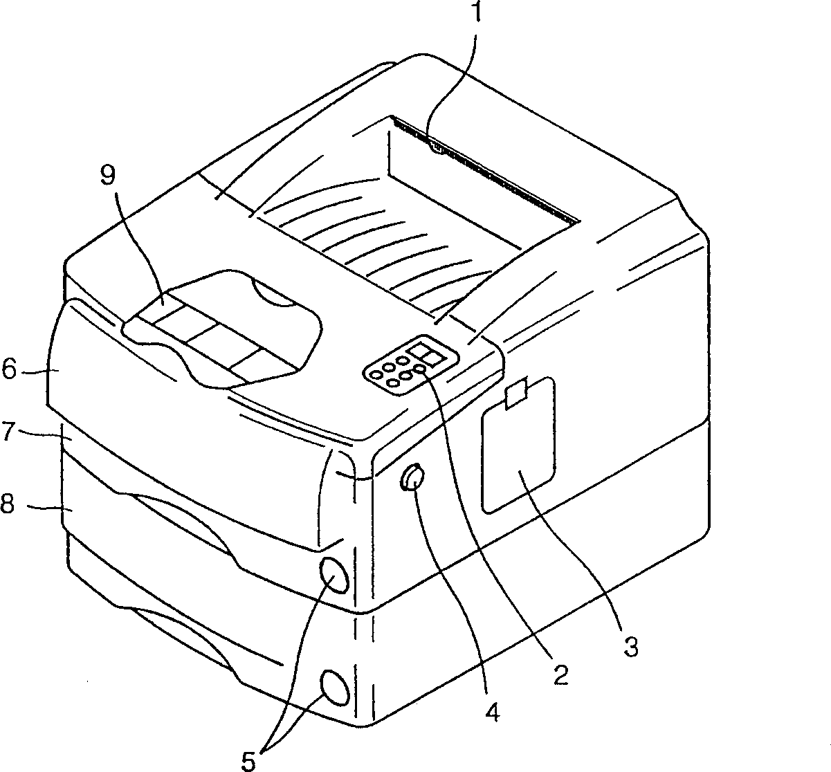
[0043] figure 1 Shown is a common electrophotographic imaging device, wherein the electrophotographic imaging device includes a paper outlet 1, a keypad 2, a control panel cover 3, a top cover open button 4, a paper display window 5, a multipurpose feeder 6, a paper cassette 7. Optional box 8 and auxiliary paper support 9.

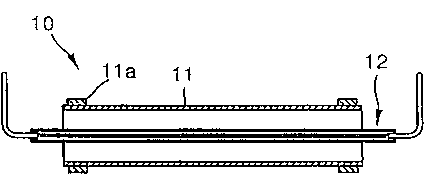
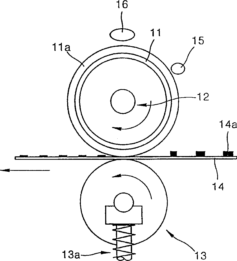
[0044] figure 2 is a sectional view of a conventional, electrophotographic image forming apparatus of a fixing roller unit using a halogen lamp as a heat source. image 3 is when figure 2 A cross-sectional view of a fixing roller in , which has a halogen lamp as a heat source and a pressure roller, when used in a general electrophotographic image forming apparatus. refer to figure 2 , the common fixing roller device 10 includes a cylindrical fixing roller 11 and a heat generator 12 , such as a halogen lamp, and the heat generator 12 is inside the fixing roller 11 . Since the outer surface of the fixing roller 11 must be able to generate heat, the f...


PUM


Abstract

A structurally improved fusing roller assembly based on the heat pipe principle is provided. The fusing roller assembly includes a fusing roller and a heat pipe coaxially mounted inside the fusing roller. A resistance heater is helically wound around the exterior cylindrical surface of the heat pipe, and rests between the inner cylindrical surface of the fusing roller and the exterior cylindrical surface of the heat pipe. The heat pipe is hermetically sealed. The sealed inner space is partially filled with a working fluid. The surface of fusing roller can be instantaneously heated up to a target fusing temperature. The fusing roller assembly can be heated up to a target fusing temperature within a shorter period of time without need for warm-up and stand-by period, so that power consumption decreases.

Description

technical field [0001] The present invention relates to a fixing roller assembly device of an electrophotographic image forming device, in particular to a fixing roller assembly of an electrophotographic image forming device capable of instantaneous heating with low energy consumption. Background technique [0002] In general electrophotographic image forming apparatuses such as copiers and laser printers, when an electrostatic charging roller near the photoreceptor drum rotates, a photosensitive material coated on the surface of the photoreceptor drum is uniformly charged. The charged photosensitive material is exposed to a laser beam scanned by a laser scanning unit (LSU), so that an electrostatic latent image is formed on the photosensitive material in a predetermined pattern. The developing device supplies toner to the photosensitive material to develop the electrostatic latent image formed on the photosensitive material into a visible toner image. ...

Claims


Application Information

Patent Timeline
IPC IPC(8): G03G15/20H05B3/00
CPCH05B3/0095G03G15/2053
Inventor 李庆雨
Owner SAMSUNG ELECTRONICS CO LTD
Learn More