
Window mounted in roof and mounting frame for mounting roof perspective structure

A technology for installing brackets and windows, applied in the field of windows, can solve the problems of increased packaging volume, inconvenience, damage to the installation brackets, etc.

Inactive Publication Date: 2002-02-06
VKR HLDG AS
View PDF2 Cites 5 Cited by
  • Summary
  • Abstract
  • Description
  • Claims
  • Application Information

AI Technical Summary

Problems solved by technology

Because this adjustment is carried out on the installation site, it is very inconvenient to pre-install the mounting bracket like this, and it is even more inconvenient because the second bracket piece of the bracket will stretch out from the window frame plane, so that the packaging volume becomes larger, and there are also Possible damage to mounting brackets or damage to other items by said brackets

Method used


Image

  • Window mounted in roof and mounting frame for mounting roof perspective structure
  • Window mounted in roof and mounting frame for mounting roof perspective structure
  • Window mounted in roof and mounting frame for mounting roof perspective structure

Examples


Embodiment Construction

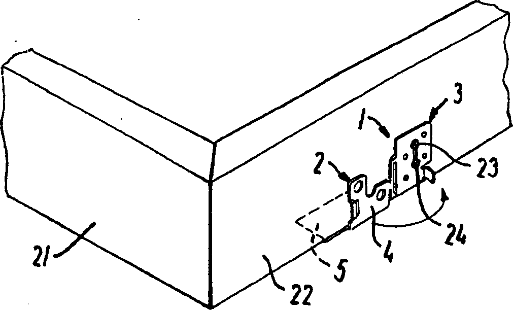
[0027] figure 1 A mounting bracket generally designated by the numeral 1 is illustrated, comprising corner bracket members 2 and a generally plate-shaped bottom member 3 . The angle bracket component 2 includes a first bracket piece 4 and a second bracket piece 5 extending from the lower end of the first bracket piece 4 approximately at right angles and integrally connected with the first bracket piece 4 . The corner bracket member 2 and the bottom member 3 are connected together by a connecting portion 6 extending from the first side end 7 of the first bracket piece 4 of the corner bracket member 2 to the first side end 8 of the bottom member 3 . The connection portion 6 includes a connection area 9, the two ends 9a, 9b of the connection area 9 are integrally connected with the first side end 8 of the bottom member 3, and the middle part 9c is connected with the first support piece 4 of the corner support member 2. The first side end 7 is connected in one piece, so that a ga...


PUM


Abstract

A window for installation in a roof includes a window frame with frame pieces and mounting brackets. Each bracket includes an angular bracket member with first and second legs connected integrally with each other, and a substantially plate-shaped base member having an opening for receiving fasteners and is connected with the outer side wall of the frame piece. The angular bracket member is connected with the base member such that, in a transportation position of the window, the second leg of the angular bracket member protrudes inwards in relation to the base member, and, in an installation position, the second leg protrudes outwards. Locking mechanism locks the first leg relative to the base member in the installation position, and adjusting mechanism adjusts the position of the angular bracket member in at least a transverse direction perpendicular to the longitudinal direction of the frame piece of the window frame.

Description

technical field [0001] The invention relates to a window installed on a roof with a sloping roof and an underlying support structure. The window includes a window frame with a frame bar and a plurality of mounting brackets, wherein the frame bar extends longitudinally and the plane defined by its outer wall is substantially perpendicular to the roof, and the mounting brackets include: a first bracket piece a corner bracket member integrally connected to the second bracket piece and a generally plate-shaped base member connected to the outer side wall of said window sill and having at least one opening for receiving a fastener , the plane defined by the bottom member is parallel to the plane defined by the outer sidewall. The corner bracket member and the bottom member are connected in such a way that when the window is in the transport position, the second bracket piece of the corner bracket member extends inwardly with respect to a plane defined by the bottom member, and whe...

Claims


Application Information

Patent Timeline
Patent Type & Authority Applications(China)
IPC IPC(8): E06B1/56E04D13/03
CPCE04D13/031
Inventor B·波尔雷森C·林格伦L·J·尼森-施米德特W·夸尔勒斯
Owner VKR HLDG AS
Learn More