Camera apparatus
A technology of a camera device and a camera element, which is applied in the directions of installation, image communication, television, etc., to achieve the effect of improving the shading property and improving the ability of light leakage
- Summary
- Abstract
- Description
- Claims
- Application Information
AI Technical Summary
Problems solved by technology
Method used
Image

Examples
no. 1 Embodiment
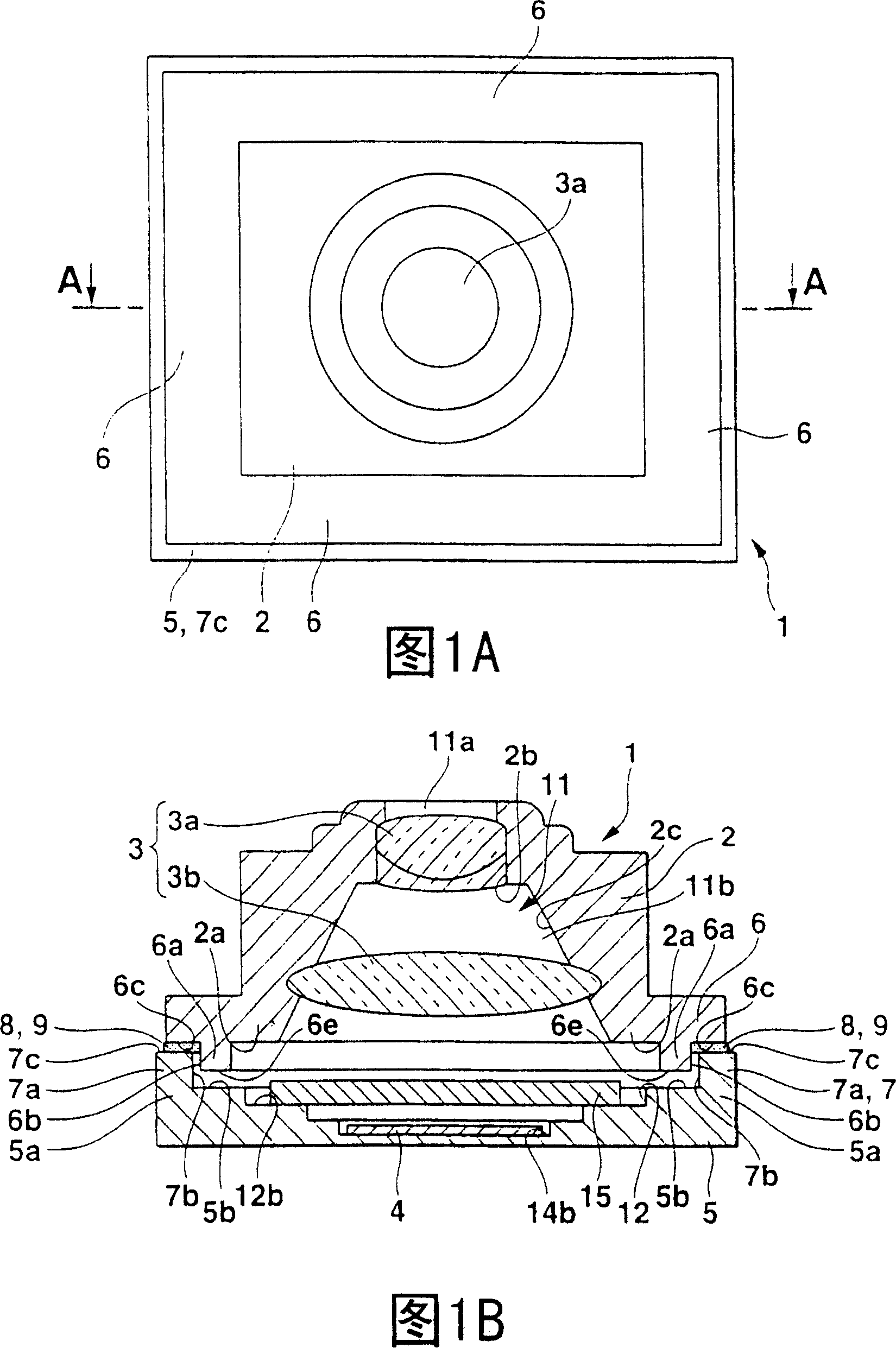
[0026] As shown in FIG. 1, the imaging device 1 of the first embodiment is an imaging device using a pan-foucus camera or the like, and has: a lens frame 2 in which an imaging lens 3 for photographing a subject is provided; and a CCD The outer package (imaging element holder) 5, in which a CCD photoelectric sensor (imaging element) 4 for photoelectric conversion of the image of the subject captured by the imaging lens 3 is installed; and the lens frame 2 and the CCD outer package 5 are joined to each other . In addition, in the following description, the subject side of the camera at the time of shooting, that is, the upper side in FIG. 1(b) is referred to as the front, and the direction away from the subject, that is, the lower side in FIG. 1(b) is referred to as the back.
[0027] The lens frame 2 has a substantially rectangular tube shape, and has a hollow portion 11 communicating in the optical axis direction, that is, in the vertical direction in FIG. 1(b). The hollow portion...
no. 2 Embodiment
[0042] Next, the second embodiment will be described.
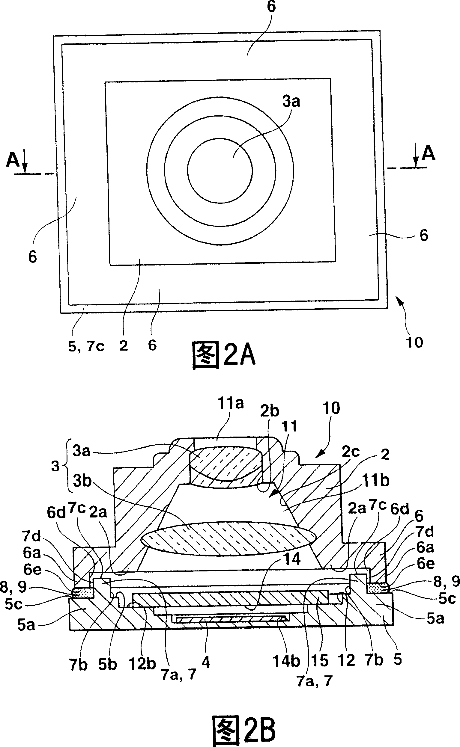
[0043] The imaging device 10 of the second embodiment, as shown in FIG. 2, is an imaging device in which the first convex portion 6a is on the outer side and the second convex portion 7a is on the inner side of the first embodiment. The same applies to the first embodiment. Therefore, in the imaging device 10, the same reference numerals are given to the same constituent elements as the imaging device 1 of the first embodiment, and the description thereof is omitted.
[0044] At the outer edge of the end surface 6c of the flange portion 6, as in the first embodiment, a first convex portion 6a protruding toward the CCD outer package 5 side is formed by extending the peripheral portion 2a of the lens frame 2.
[0045] The front edge of the CCD outer package 5 is provided with a stepped portion 5c recessed rearward, and the height is approximately equal to the height of the first stepped portion 5b from the front where the reces...
no. 3 Embodiment
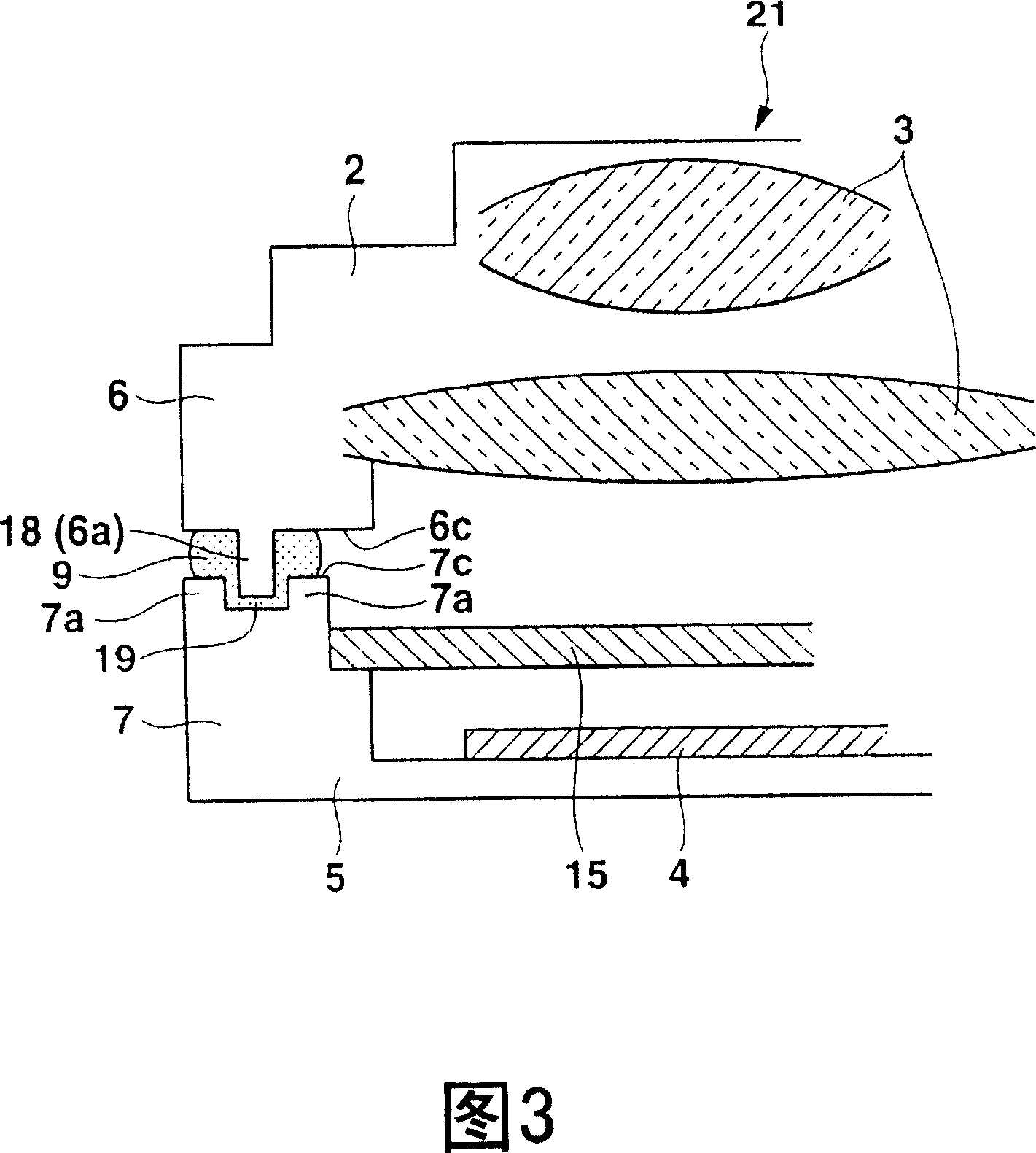
[0052] Next, a third embodiment will be described with reference to FIG. 3.
[0053] In the imaging device 21 of the third embodiment, the lens frame 2 and the imaging lens 3 arranged inside, the CCD outer package (imaging element holder) 5, and the CCD photoelectric sensor (imaging element) 4 and OLPA 15 arranged inside it Etc. are the same as the first and second embodiments. Therefore, while simplifying their illustrations, the same components as those of the imaging devices 1 and 10 of the first and second embodiments are given the same drawing numbers, and The description is omitted.
[0054] The third embodiment differs from the first and second embodiments in the structure of the lens frame joint 6 and the outer package joint (holder joint) 7. Therefore, these differences will be described in detail below.
[0055] That is, a rib (projection) 18 is formed on the end surface 6c of the lens frame joining portion 6 to extend along the periphery of the lens frame 2. The rib 18 ...
PUM
 Abstract
Description
Claims
Application Information
 - R&D
- Intellectual Property
- Life Sciences
- Materials
- Tech Scout
- Unparalleled Data Quality
- Higher Quality Content
- 60% Fewer Hallucinations
Browse by: Latest US Patents, China's latest patents, Technical Efficacy Thesaurus, Application Domain, Technology Topic, Popular Technical Reports.
© 2025 PatSnap. All rights reserved.Legal|Privacy policy|Modern Slavery Act Transparency Statement|Sitemap|About US| Contact US: help@patsnap.com