Coil driving method and apparatus and magnetic resonance imaging device
A coil drive and coil technology, applied in magnetic resonance measurement, measurement of magnetic variables, medical science, etc., can solve the problems of sensitivity fluctuation, unbalance, coupling unbalance, etc.
- Summary
- Abstract
- Description
- Claims
- Application Information
AI Technical Summary
Problems solved by technology
Method used
Image
Examples
no. 1 example
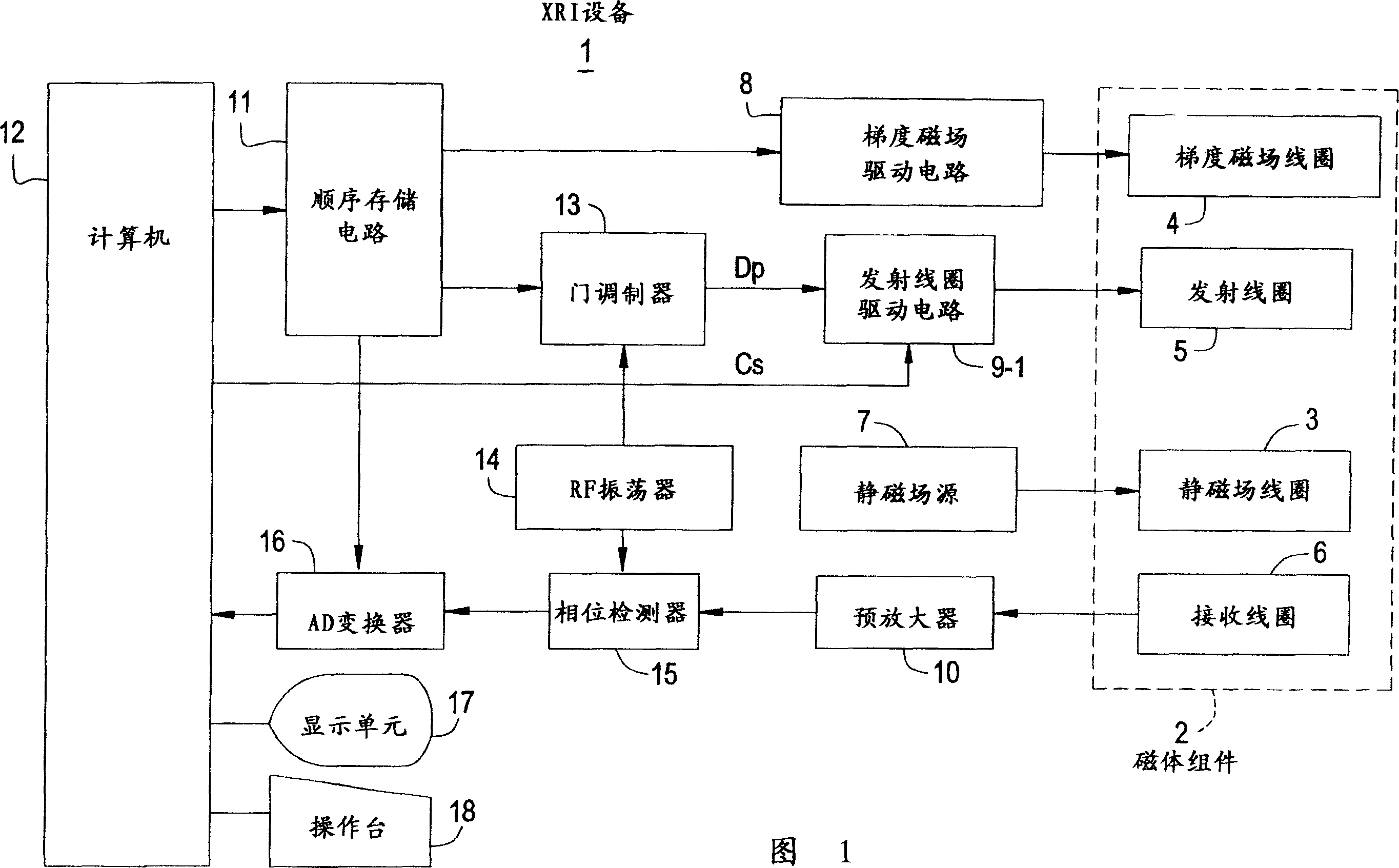
[0105] FIG. 1 is a block diagram showing a configuration of an MRI apparatus according to a first embodiment of the present invention.
[0106] In the present MRI apparatus 1, the magnet assembly 2 has a space (hole) for inserting a sample thereinto. Static magnetic field coil 3 used to apply a constant static magnetic field to the sample, gradient or ramped magnetic field coil 4 used to generate gradient or ramped magnetic fields on the slice axis, guide axis and phase axis, used to provide RF pulses to excite nuclei in the sample The spinning transmitting coil 5 and the receiving coil 6 used to detect the NMR signal from the sample are arranged in the magnet assembly 2 to surround the above-mentioned space.
[0107] The static magnetic field coil 3 is electrically connected to a static magnetic field source 7 . The gradient magnetic field coil 4 is electrically connected to a gradient or ramp magnetic field drive circuit or driver 8 . The transmitting coil 5 is electricall...
no. 2 example
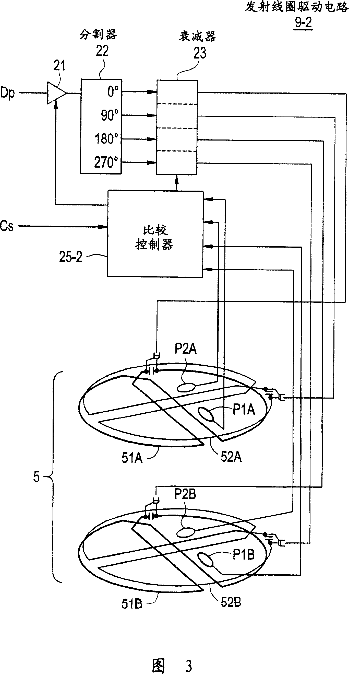
[0125] FIG. 3 is a schematic diagram showing a transmission coil drive circuit 9-2 and a transmission coil 5 according to the second embodiment. Incidentally, the same structural elements as those used in the first embodiment are denoted by the same numerals, respectively, so that their descriptions can be simplified.
[0126] The transmitting coil driving circuit 9-2 includes an amplifier 21, a divider 22, an attenuator 23, corresponding sensing coils P1A, P2A, P1B and P2B placed near the four coils constituting the transmitting coil 5, and a comparator controller 25- 2. It is used to sample and compare the voltage induced by the corresponding sensing coils P1A, P2A, P1B and P2B at the timing corresponding to the control signal Cs sent by the computer 12, and adjust the attenuation rate of the attenuator 23 to make the voltage according to The predetermined ratio is changed accordingly, and the output of the amplifier 21 is controlled according to each decay rate.
[0127] T...
no. 3 example
[0133] FIG. 4 is a schematic diagram showing a transmission coil drive circuit 4-3 and a transmission coil 5 according to the third embodiment. Incidentally, the same structural elements as those used in the first embodiment are denoted by the same numerals, respectively, so that their descriptions can be simplified.
[0134] The transmitting coil drive circuit 9-3 includes an amplifier 21, a divider 22, and a setting controller 26 for adjusting the respective attenuation rates of the attenuator 23 so that each attenuation rate becomes set by the control signal Cs sent from the computer 12. value, and the output of the amplifier 21 is controlled according to the attenuation rate.
[0135] The transmitting coil 5 includes an upper coil 5A and a lower coil 5B, which are vertically opposed to each other.
[0136] The upper coil 5A includes an upper first coil 51A and an upper second coil 52A.
[0137] The lower coil 5B includes a lower first coil 51B and a lower second coil 52B...
PUM
 Abstract
Description
Claims
Application Information
 - R&D Engineer
- R&D Manager
- IP Professional
- Industry Leading Data Capabilities
- Powerful AI technology
- Patent DNA Extraction
Browse by: Latest US Patents, China's latest patents, Technical Efficacy Thesaurus, Application Domain, Technology Topic, Popular Technical Reports.
© 2024 PatSnap. All rights reserved.Legal|Privacy policy|Modern Slavery Act Transparency Statement|Sitemap|About US| Contact US: help@patsnap.com


