Elevator braking device

A brake device and elevator technology, which is applied in hoisting devices, brake types, drum brakes, etc., can solve problems such as brake inaction, achieve reliable braking and release of brakes, and reduce impact noise

Inactive Publication Date: 2007-01-24
MITSUBISHI ELECTRIC CORP
View PDF8 Cites 0 Cited by
  • Summary
  • Abstract
  • Description
  • Claims
  • Application Information

AI Technical Summary

Problems solved by technology

Therefore, since the above-mentioned difference is reduced by making the predetermined value close to the reaction force of the brake spring, although the brake can reduce the noise when the brake is released and operated, the release action and the operation action are elongated, or further caused by There is also a problem that the brake may not operate due to the resistance when the movable iron core moves

Method used


Image

  • Elevator braking device
  • Elevator braking device
  • Elevator braking device

Examples


Embodiment Construction

[0035] The present invention will be described in more detail with reference to the accompanying drawings. In each figure, the same reference numerals are attached to the same or corresponding parts, and their repeated descriptions are appropriately simplified or omitted.

[0036] [Embodiment 1]

[0037] Figure 1 to Figure 5 Embodiment 1 of the brake device of the elevator of this invention is shown.

[0038] In this first embodiment, an urging elastic body composed of a coil spring is attached to a braking device used in a hoisting machine of an elevator.

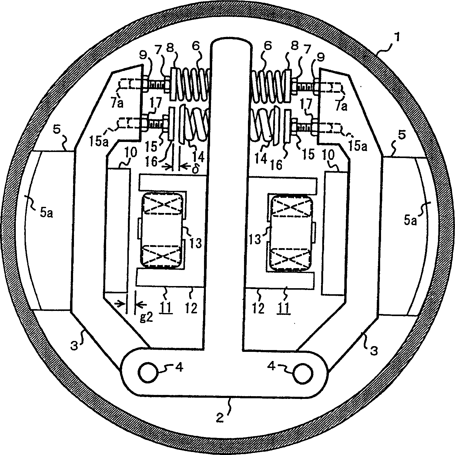
[0039] figure 1 Among them, 1 is the brake wheel installed on the winch, which is also used as the rotor of the drive motor of the winch. 2 is a frame for installing the structural parts of the brake on the inside of the brake wheel 1, 3 is a pair of arms that are supported on the frame 2 freely by using pin 4 at one end, and 5 is installed on the outside of the arm 3. The arm 3 swings to move forward and backward fr...


PUM


Abstract

This invented elevator braked device makes the brake scotch move forward with a brake spring to further brake a brake wheel and releases the brake by attracting a movable iron core with an electromagnetic iron to force the brake scotch to move backward and is mounted with a reinforcing by the counter force with increasing rate greater than the attraction force of the magnetic iron arisen from reduction of slot. When releasing the brake, since the iron balances the counter force caused by the combined counter force of reinforcing elastic unit and the brake spring, at the same time, it attracts the movable iron core steadily along with the increasing of the exciting current, the striking noise is reduced.

Description

technical field [0001] The present invention relates to a braking device for an elevator that reduces noise during braking or releasing the brake. Background technique [0002] In a brake device for an elevator, especially a brake device for braking a hoist, an electromagnet is deenergized and a brake pad is pressed against a brake wheel by a brake spring, whereby a braking state is established by friction. Also, when the brake is released, the electromagnet is powered to attract the movable iron core, and the brake shoe is separated from the brake wheel against the force of the brake spring to release the brake. [0003] However, the electromagnet has a characteristic that the attractive force increases as the distance from the movable iron core decreases. Therefore, when the brake is released, the movable iron core is attracted by the electromagnet to generate a crashing sound. Also, during braking, the brake pads are pressed against the brake wheels by the brake springs...

Claims


Application Information

Patent Timeline
IPC IPC(8): B66D5/08B66B11/08B66B1/32F16D51/10F16D65/27B66B11/04B66D5/30F16D65/14F16D65/22
CPCB66D5/30F16D2121/22F16D51/20B66D5/08
Inventor 冈田浩二
Owner MITSUBISHI ELECTRIC CORP
Why Eureka
Try Eureka