Printing quality detecting device for printer
A printing quality and detection device technology, applied in printing machines, general parts of printing machinery, measuring devices, etc., can solve problems such as error detection, detection device error detection, etc., to increase reliability and prevent inappropriate operations and errors The effect of detection
- Summary
- Abstract
- Description
- Claims
- Application Information
AI Technical Summary
Problems solved by technology
Method used
Image

Examples
no. 1 example
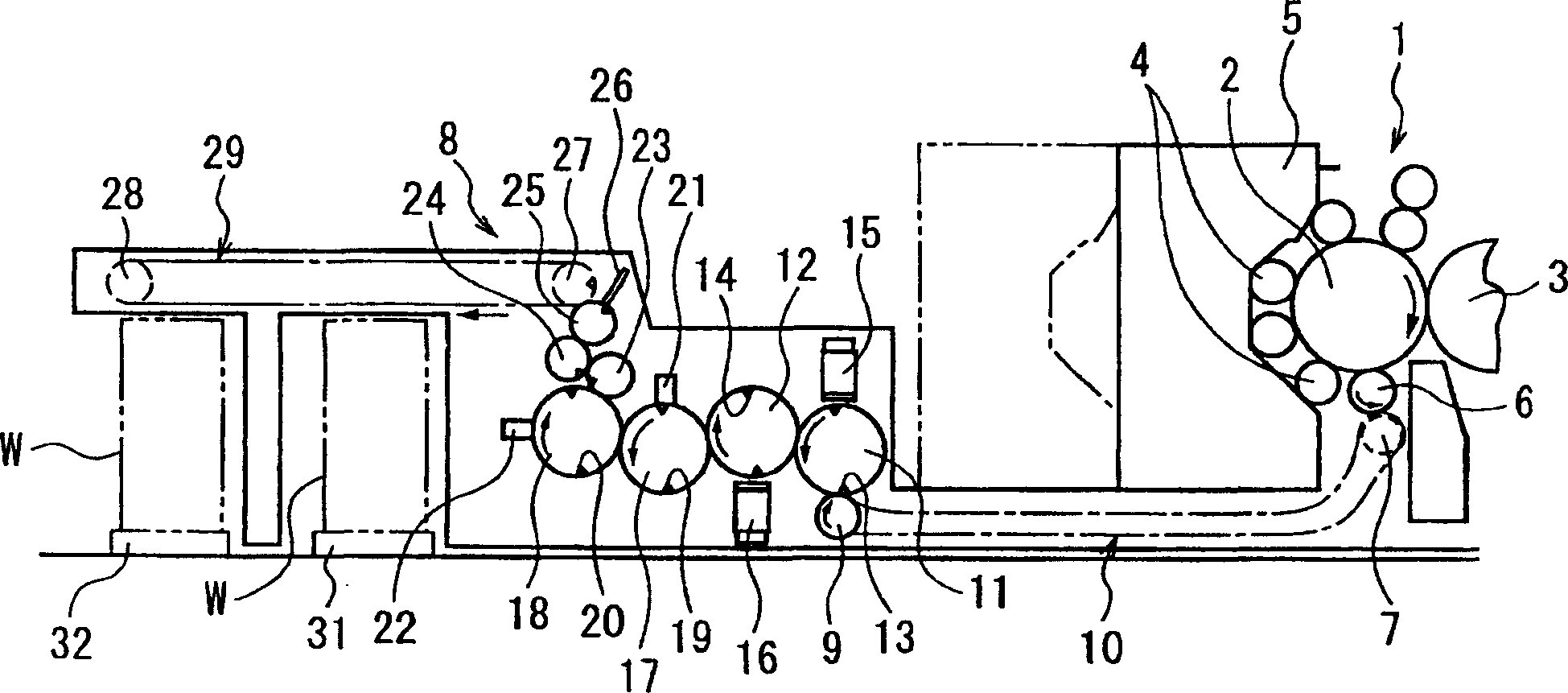
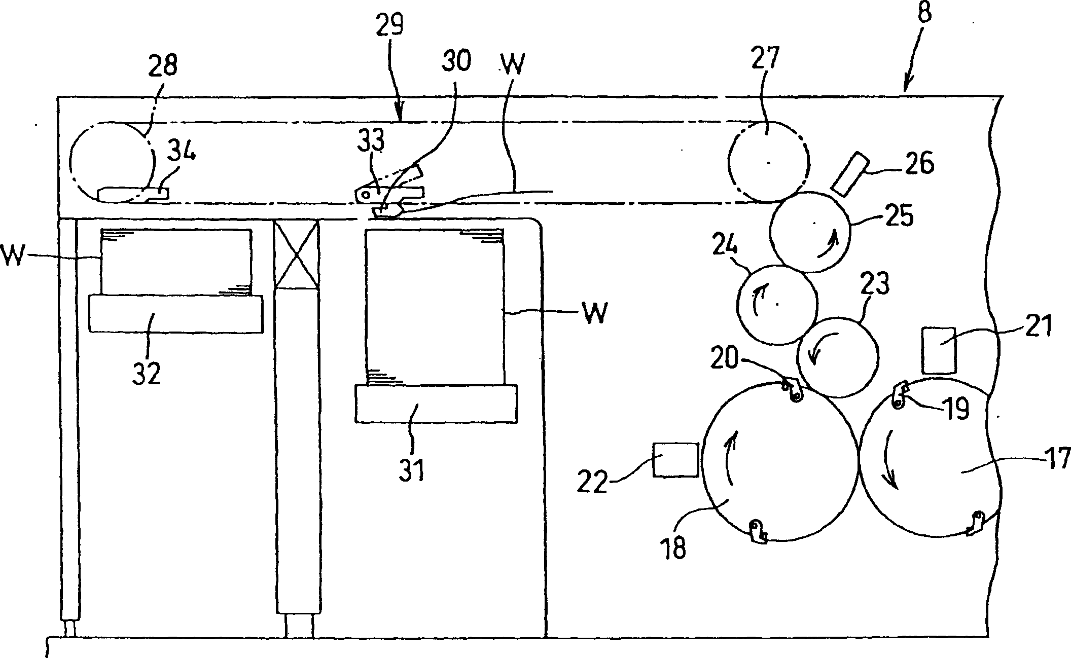
[0030] figure 1 It is a side view showing the essential parts of the four-color perfecting printing machine of the first embodiment of the present invention, figure 2 is an enlarged side view of the conveyor in the essential part of the printing press.
[0031] exist figure 1 In the illustrated printing unit 1 of a four-color perfecting printing machine, an impression cylinder 2 with an adhesive film with a clamping device (not shown) and a blanket cylinder 3 without a clamping device are rotatably supported on an approximately horizontal state, their peripheral surfaces are in contact with each other. Four plate cylinders are placed on the circumferential surface of the impression cylinder 2 with a film. Likewise, four plate cylinders (not shown) are placed on the circumferential surface of the blanket cylinder 3 . The inking device 5 , away from and out of contact with the plate cylinder 4 , is arranged movably so as to be able to supply ink and water when in contact wi...
no. 2 example
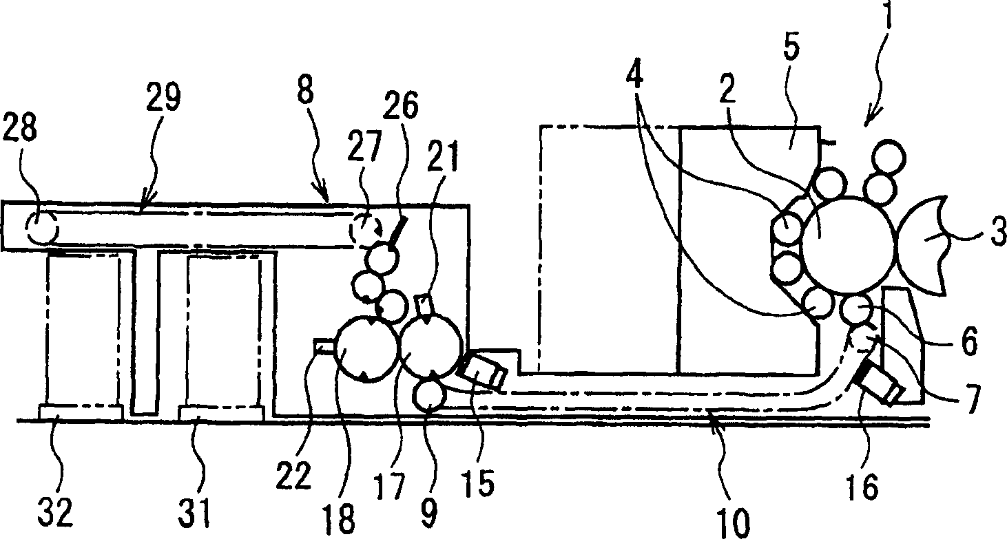
[0043] image 3 It is a side view showing the essential parts of the four-color perfecting printing machine according to the second embodiment of the present invention. Figure 4 is a diagram illustrating the principle of camera installation.
[0044] In this embodiment, the drying cylinders 11 and 12 in the first embodiment are removed; the back side UV device 16 is arranged on the opposite side of the conveying path of the first conveying chain 10; the face side UV device 15 is arranged on the first detection cylinder 17, so that the ultraviolet radiation from the surface side UV device 15 is blocked by the first detection roller 17, thus preventing the radiation from entering the surface side detection camera 21.
[0045] That is to say, the positional relationship between the face side UV device 15 and the face side detection camera 21 makes the ultraviolet radiation from the face side UV device 15 equipped with two bulbs 40a and 40b and a lampshade 41 be blocked by the f...
no. 3 example
[0048] Figure 5 It is a side view of essential parts of a four-color perfecting printing machine showing a third embodiment of the present invention.
[0049] In this embodiment, the impression cylinder 2 with adhesive film in the second embodiment is used as a transfer roller, the backside UV device 16 is provided on the circumferential surface of the transfer roller 2, and the transfer roller 6 is used as a transfer roller, The face-side UV device 15 is provided opposite to the circumferential surface of the transfer drum 6 . Since other structures are the same as those of the second embodiment, and image 3 The same members shown in are denoted by the same numerals, so their repeated descriptions are omitted.
[0050] According to this embodiment, the same actions and effects as those of the second embodiment can be obtained.
PUM
 Abstract
Description
Claims
Application Information
 - R&D
- Intellectual Property
- Life Sciences
- Materials
- Tech Scout
- Unparalleled Data Quality
- Higher Quality Content
- 60% Fewer Hallucinations
Browse by: Latest US Patents, China's latest patents, Technical Efficacy Thesaurus, Application Domain, Technology Topic, Popular Technical Reports.
© 2025 PatSnap. All rights reserved.Legal|Privacy policy|Modern Slavery Act Transparency Statement|Sitemap|About US| Contact US: help@patsnap.com