Fault tolerant power supply conversion circuit

A power conversion and circuit technology, applied in the direction of circuits, adjusting electrical variables, emergency protection circuit devices, etc., can solve problems such as damage to switching devices and lower circuit efficiency

Inactive Publication Date: 2006-12-20
INDUCTOTHERM INDS
View PDF1 Cites 0 Cited by
  • Summary
  • Abstract
  • Description
  • Claims
  • Application Information

AI Technical Summary

Problems solved by technology

[0007] The present invention solves the problem of premature damage to switching devices due to overvoltage conditions caused by short circuits in inductive loads without reducing circuit efficiency under normal operating conditions and without subjecting switching devices to high levels of current to avoid overvoltage

Method used


Image

  • Fault tolerant power supply conversion circuit
  • Fault tolerant power supply conversion circuit
  • Fault tolerant power supply conversion circuit

Examples


Embodiment Construction

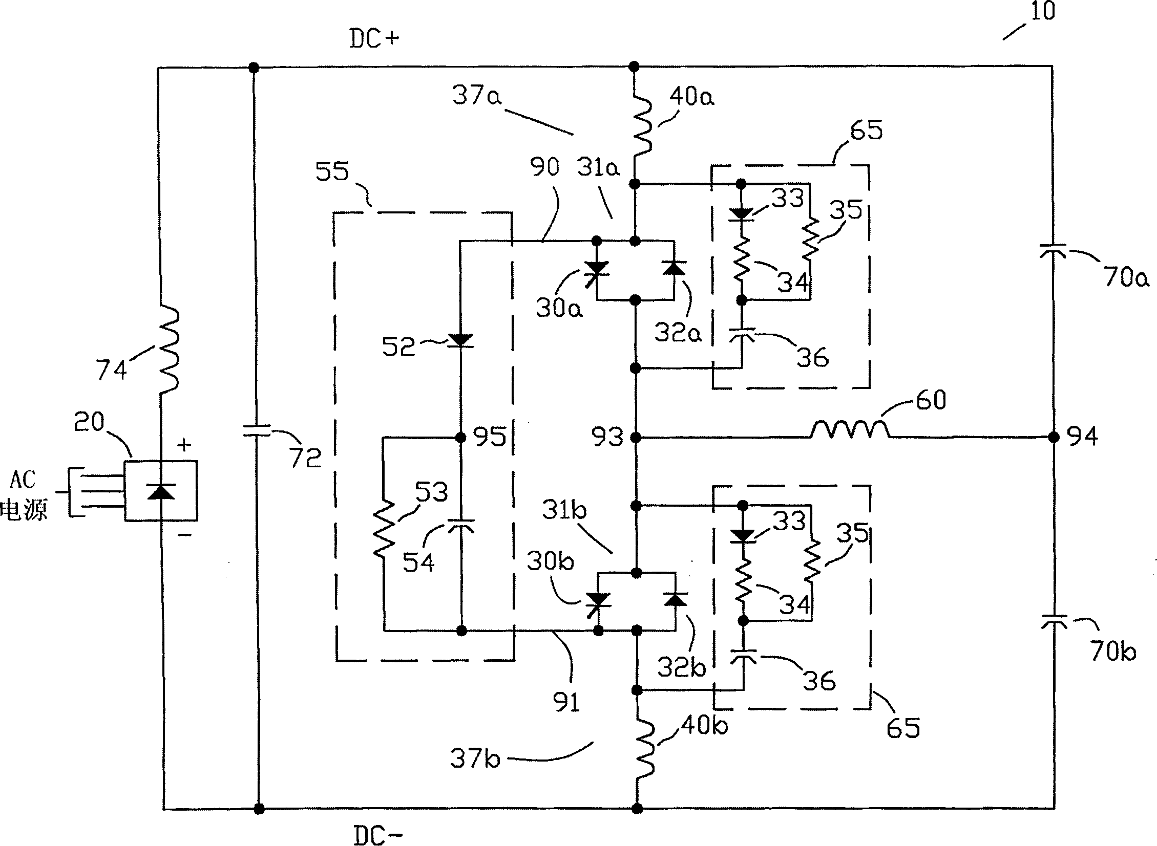
[0025] Referring to the drawings, wherein like numerals refer to like elements, Figure 2a An example of the fault-tolerant power conversion circuit 10 of the present invention is shown. Each of the two switching devices 30a and 30b (such as, but not limited to, SCRs) is connected in antiparallel with antiparallel diodes 32a and 32b to form switching circuits 31a and 32b, respectively. The first terminals of these switch circuits are connected together at switch common connection point 93 . First terminals of the current limiting reactors 40a and 40b are respectively connected to second terminals of the switching circuits 31a and 31b to form switching modules 37a and 37b, respectively. The second terminals of the current limiting reactors 40a and 40b are connected to the positive and negative dc buses (output lines) of the dc power supply 20, respectively. The power supply includes a rectifier bridge 20 (shown schematically) with optional series filter inductor 74 and parall...


PUM


Abstract

A fault current tolerant power supply circuit having a dc power source and switching devices for inverting dc current from the source into ac load current includes a protective circuit for protecting the switching devices from overvoltage conditions when an inductive load is short-circuited. The protective circuit uses a capacitive component to absorb charge during a short circuit to protect non-conducting switching devices from an overvoltage condition.

Description

[0001] Cross References to Related Applications [0002] This application claims the benefit of US Provisional Application No. 60 / 311,822, filed August 13,2001. technical field [0003] The present invention relates to a power supply circuit, in particular for supplying ac current to an inductive load, for example used in induction heating or induction melting applications, where said inductive load may experience possible short circuits, depending on the power used in the power supply The layout of the power supply, the high level of the fault voltage, the fault current passing through, and the switching devices used for power supply. Background technique [0004] A conventional series resonant dc-ac inverter power supply circuit for an induction furnace or other substantially inductive impedance load consists of a dc source and an inverter. The inverter has one or more pairs of switch circuits connected in series. Each switching circuit includes a series combination of a...

Claims


Application Information

Patent Timeline
Patent Type & Authority Patents(China)
IPC IPC(8): H02M3/315H02M3/24H02M5/42H02M7/44H02M7/68H02M7/515H02M7/521H02H7/122H02M1/34H02M7/519H03K17/0814
CPCH02M7/519H03K17/08144H02M2001/348H02M1/34H02M2001/325H02M1/325H02M1/348H02M7/505H03K17/08
Inventor 弗拉迪米尔·V·纳多奥列格·S·菲什曼
Owner INDUCTOTHERM INDS
Why Eureka
Try Eureka